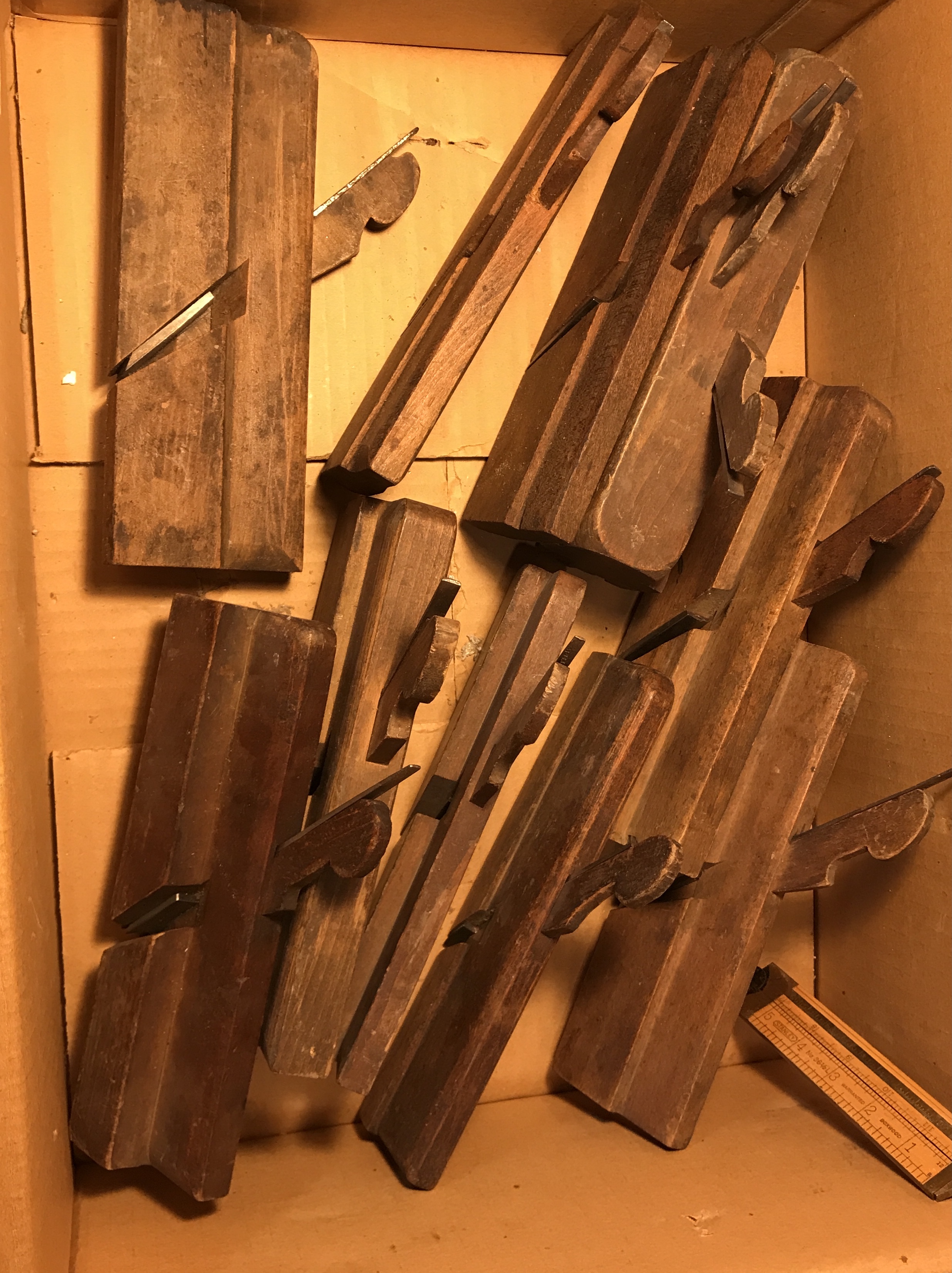
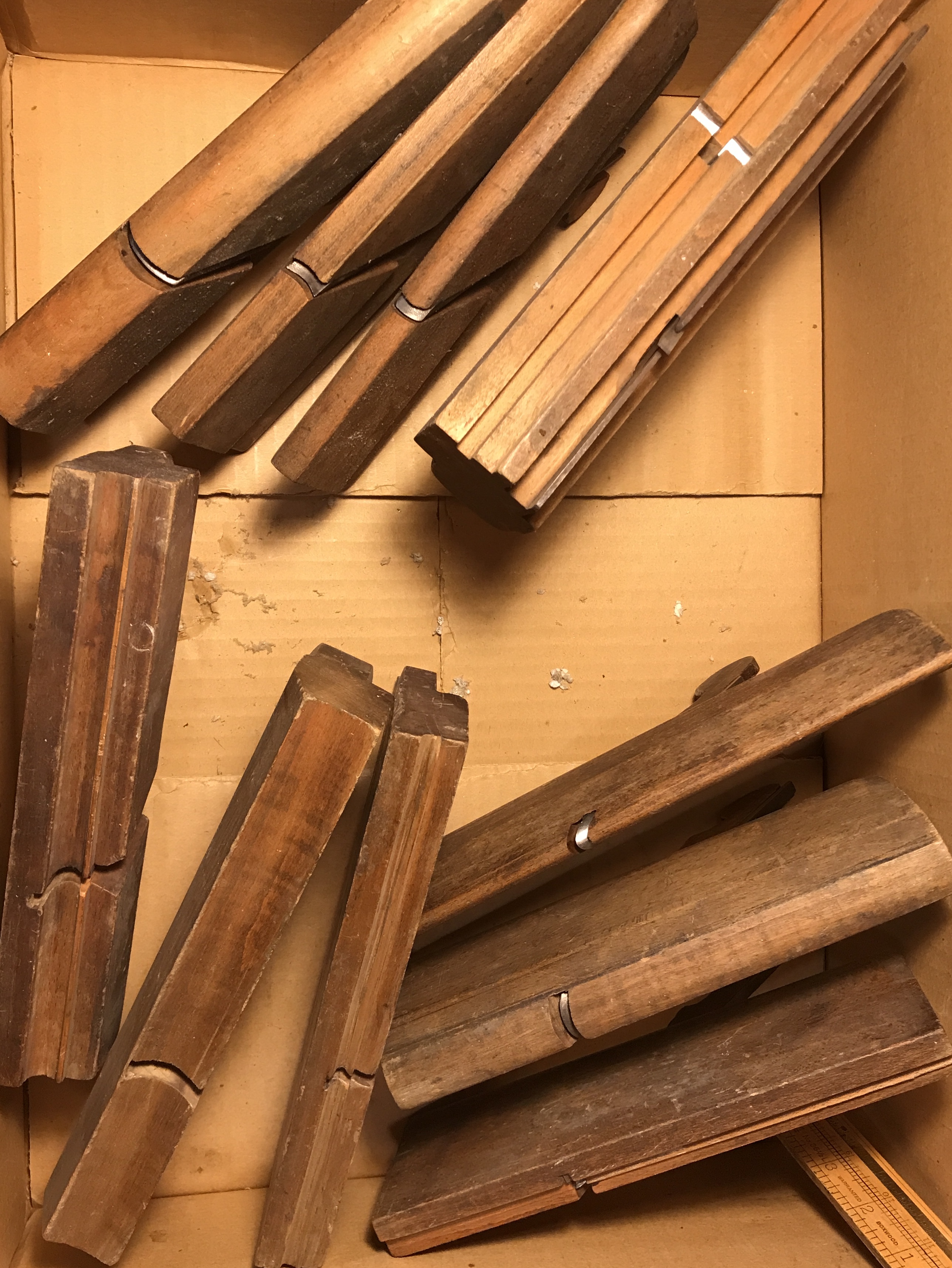
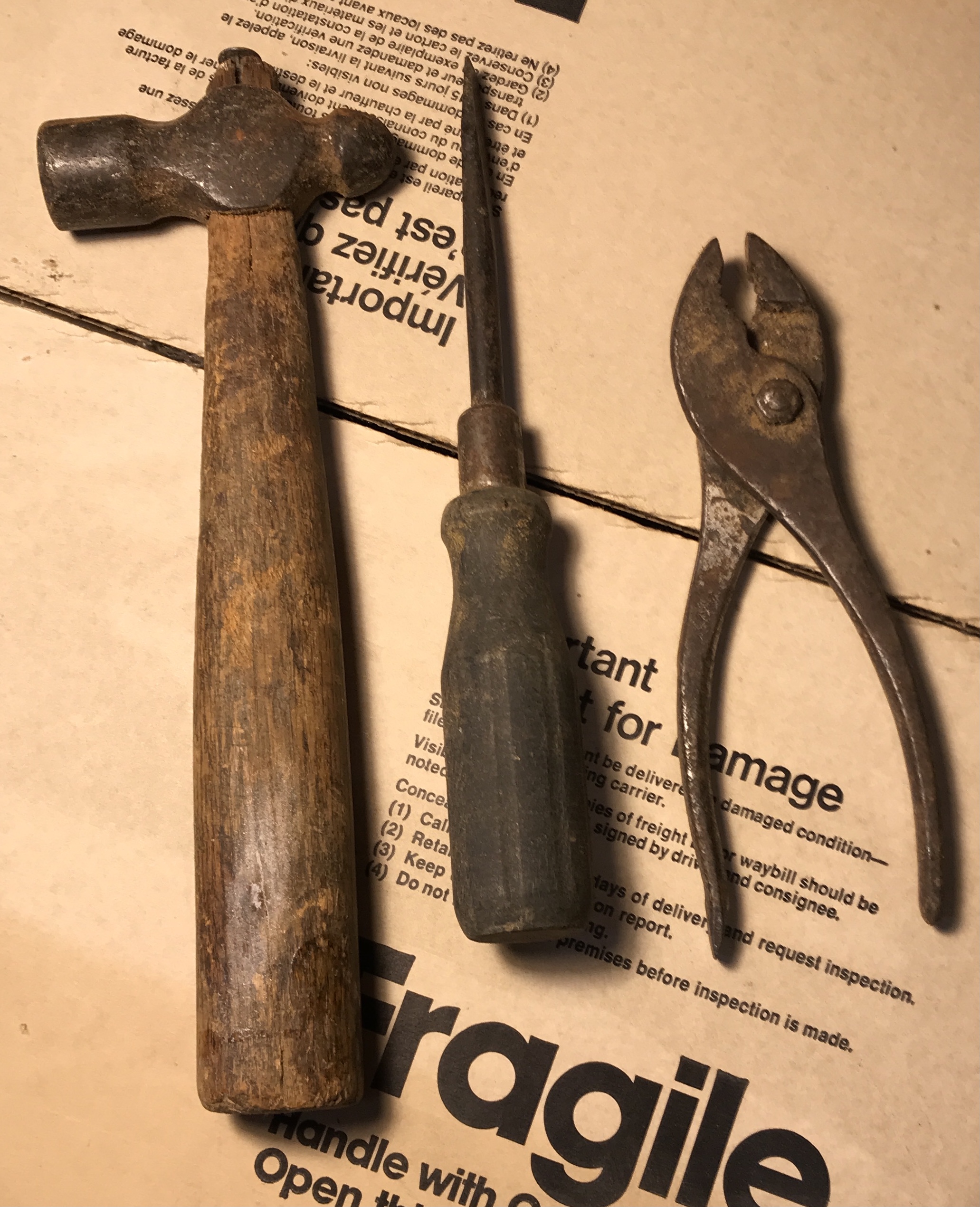
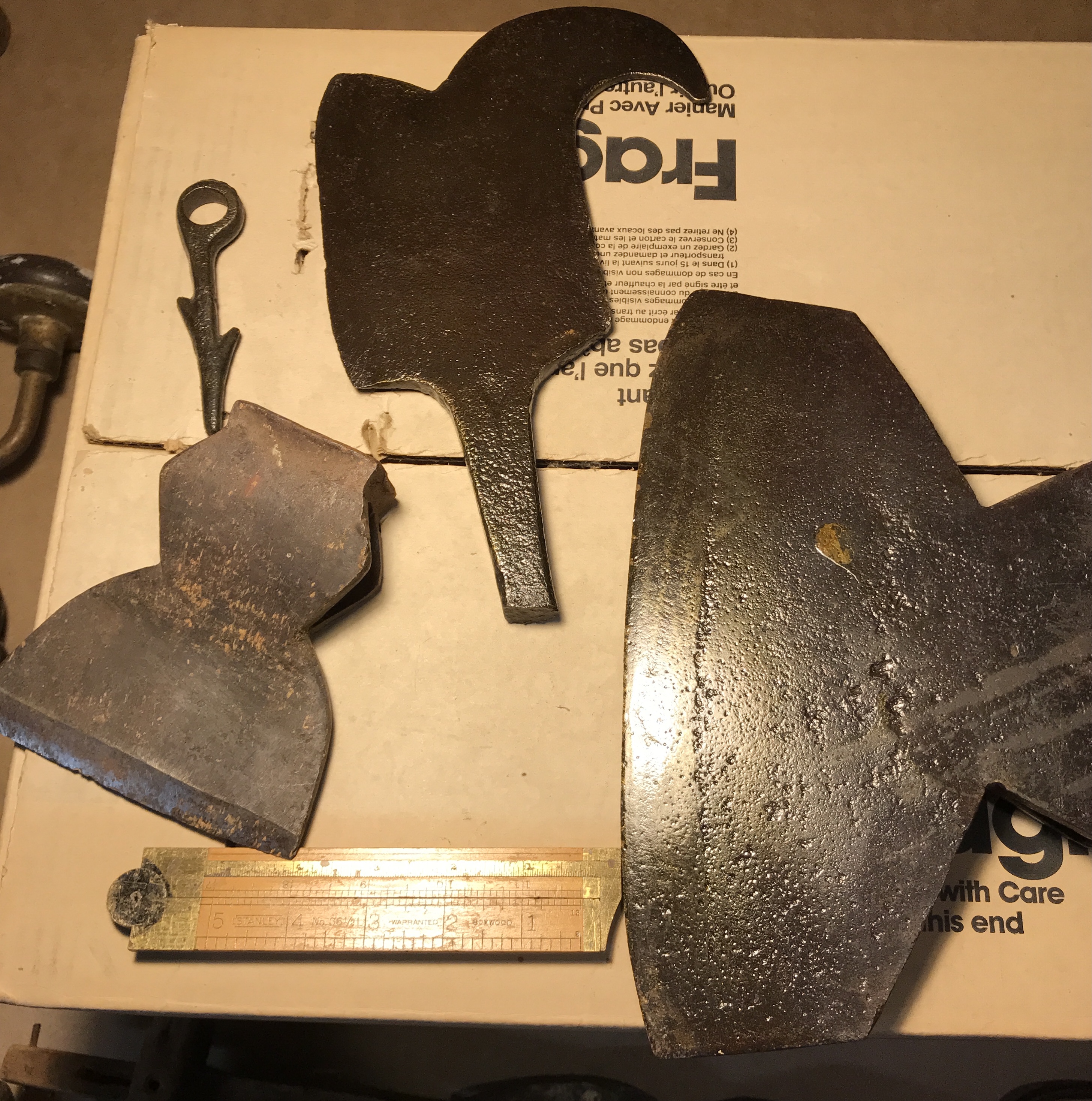
I am planning on taking a weekend course next year at Marc Adams on using and tuning old planes. I remembered that I had a box of old tools in the garage from Uncle Bob, who probably got them from my grandfather, William Webster. I opened the box and found a huge wooden sole plane, many different shapes of wooden jointers and other assorted tools. Pictures are included below.
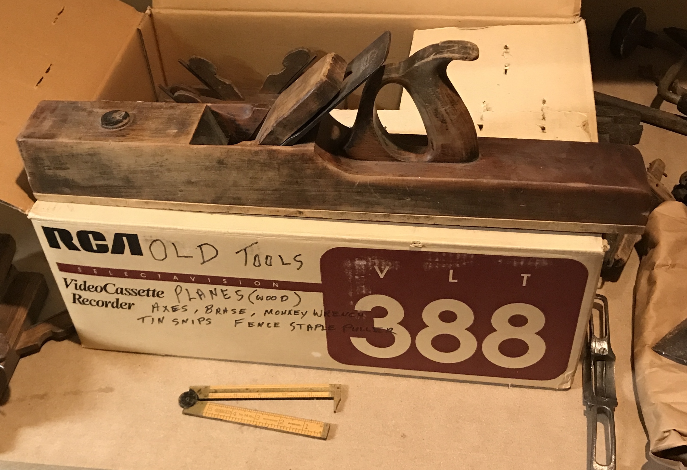
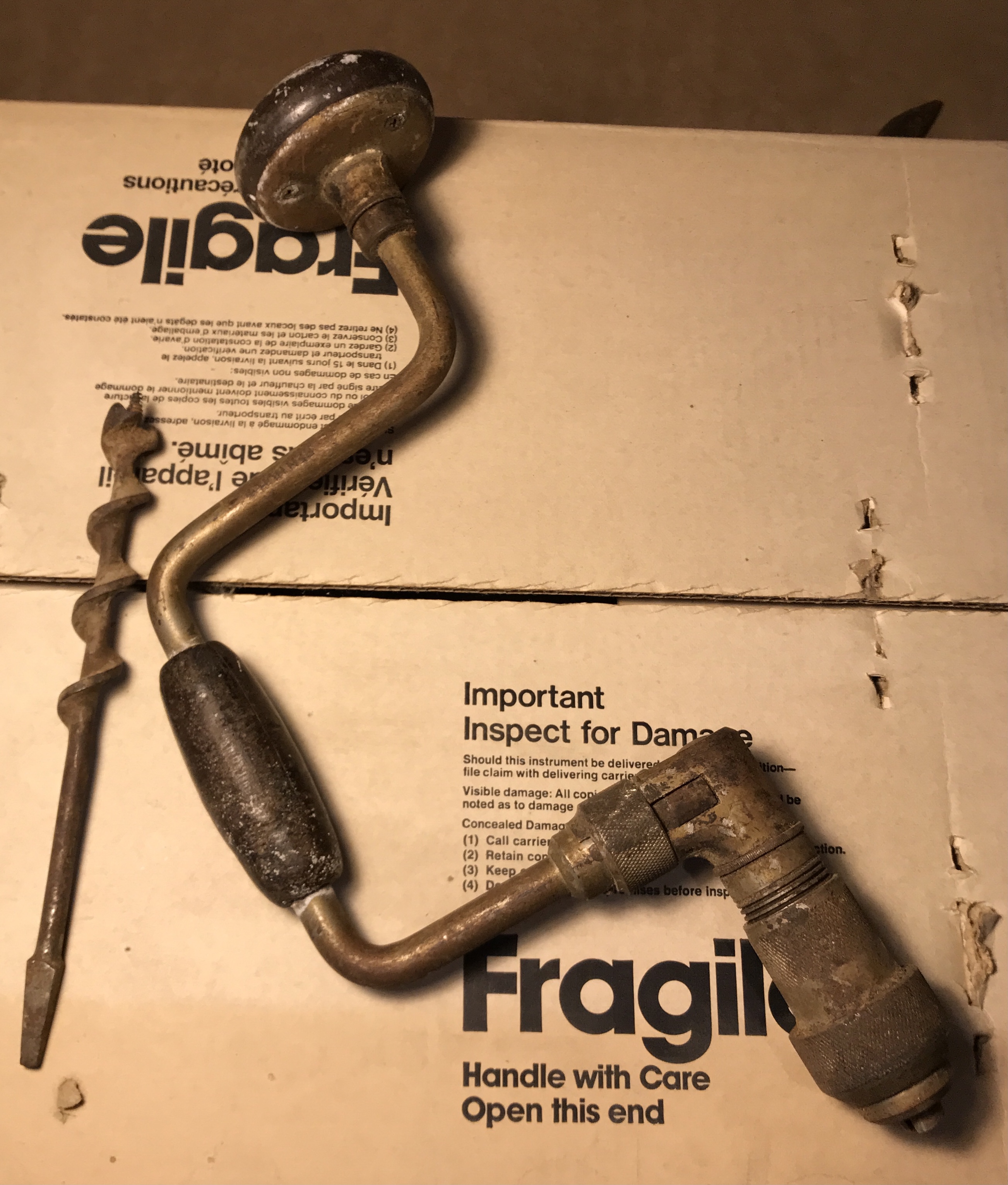
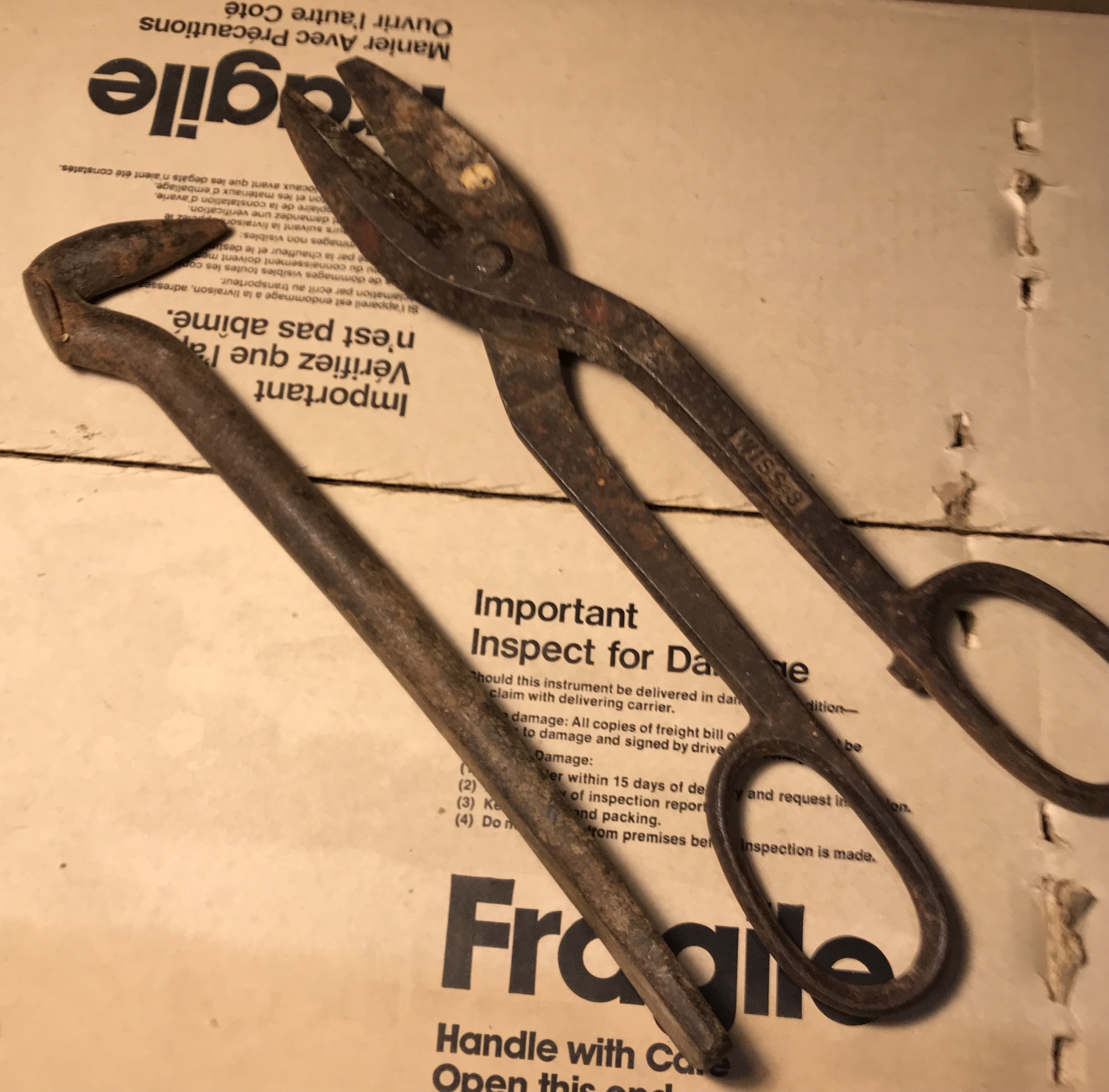
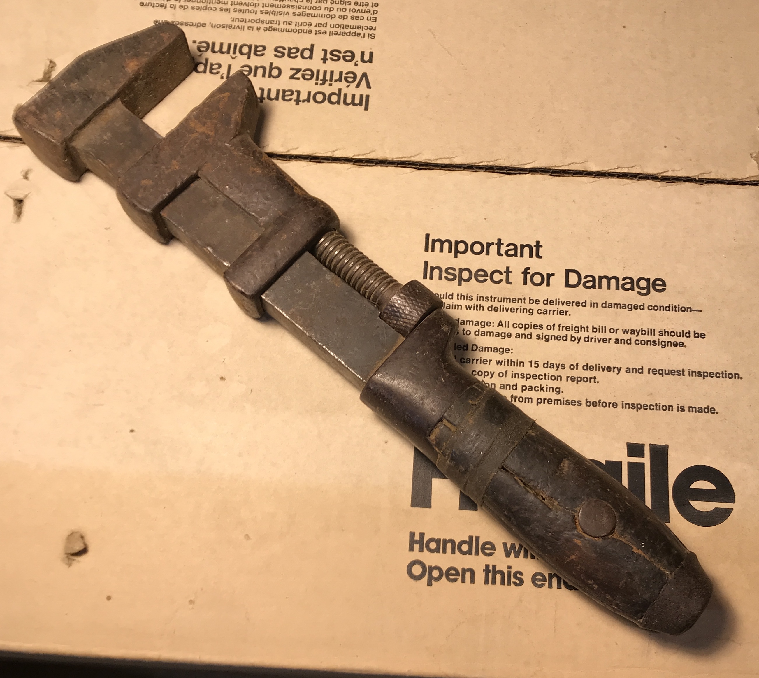
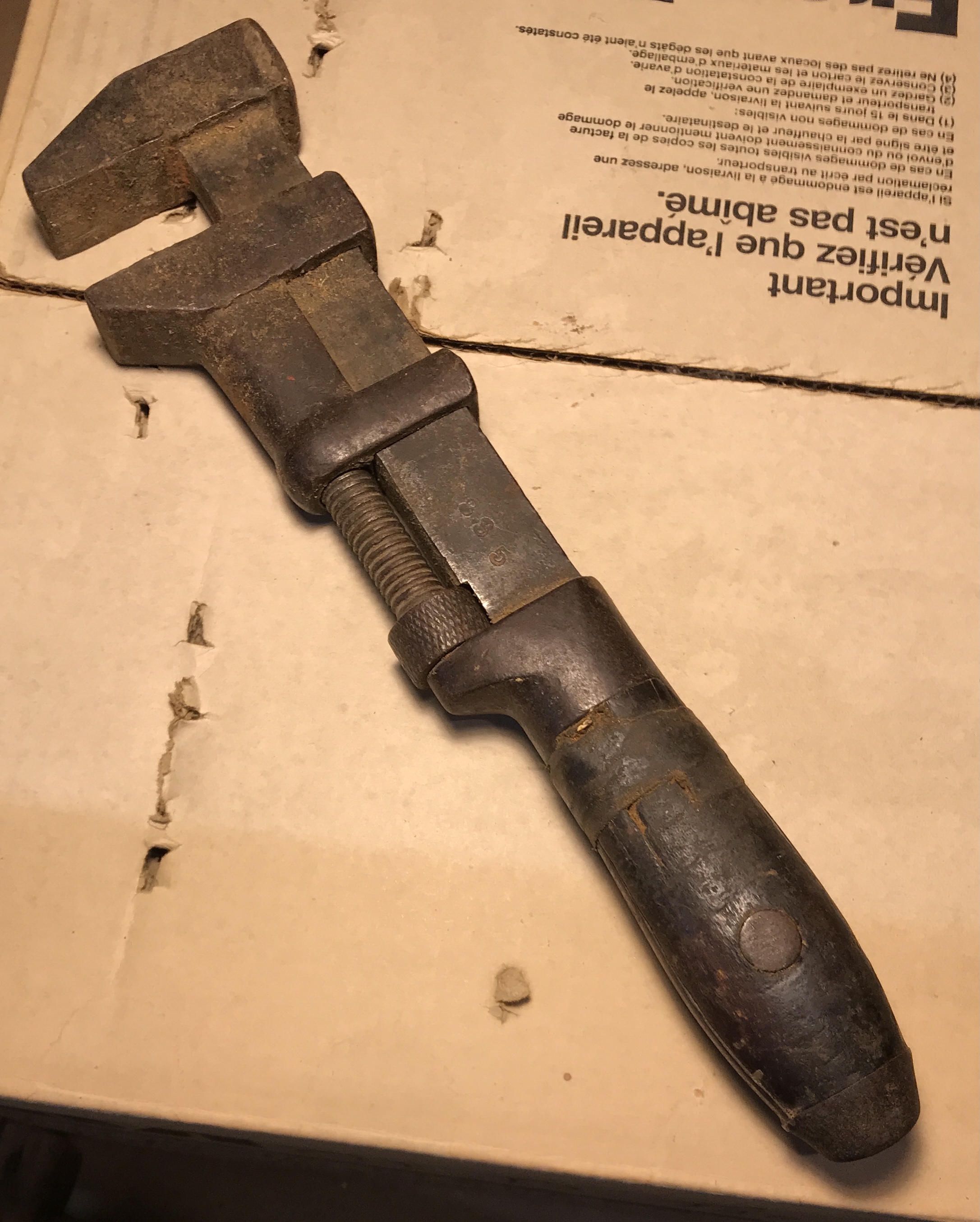
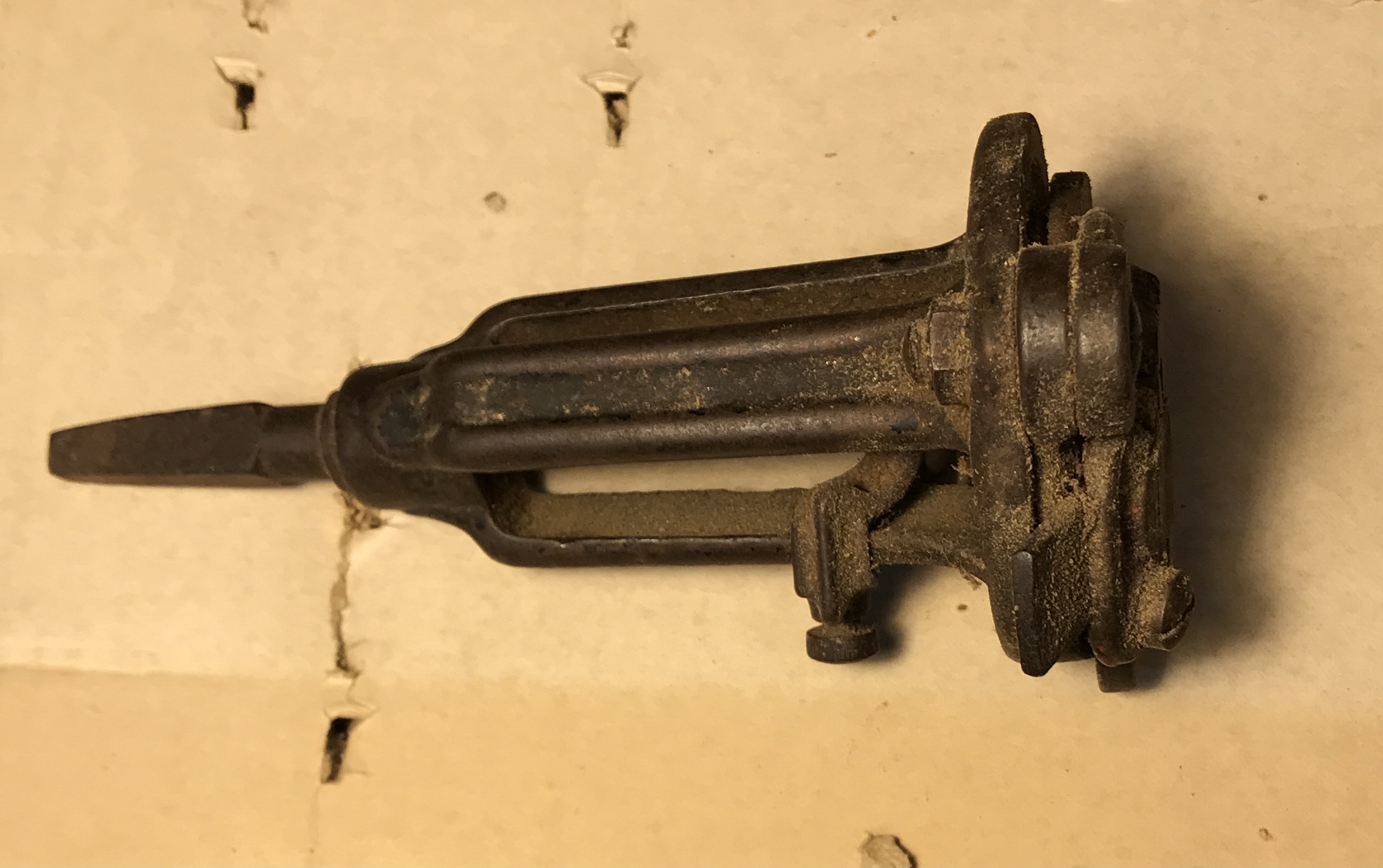
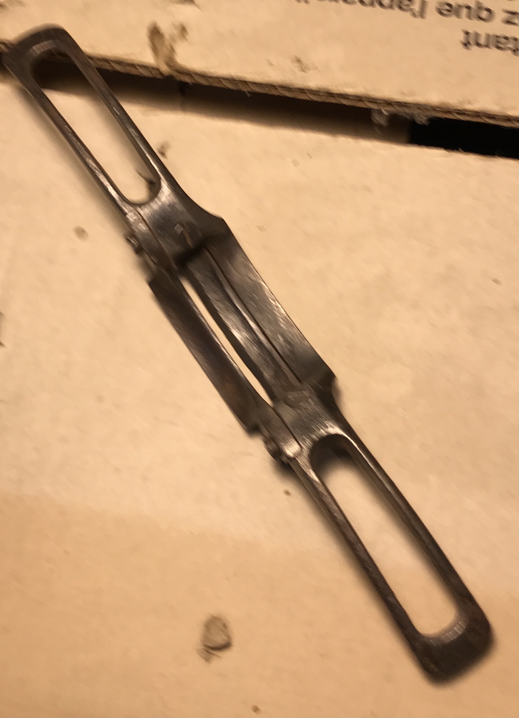
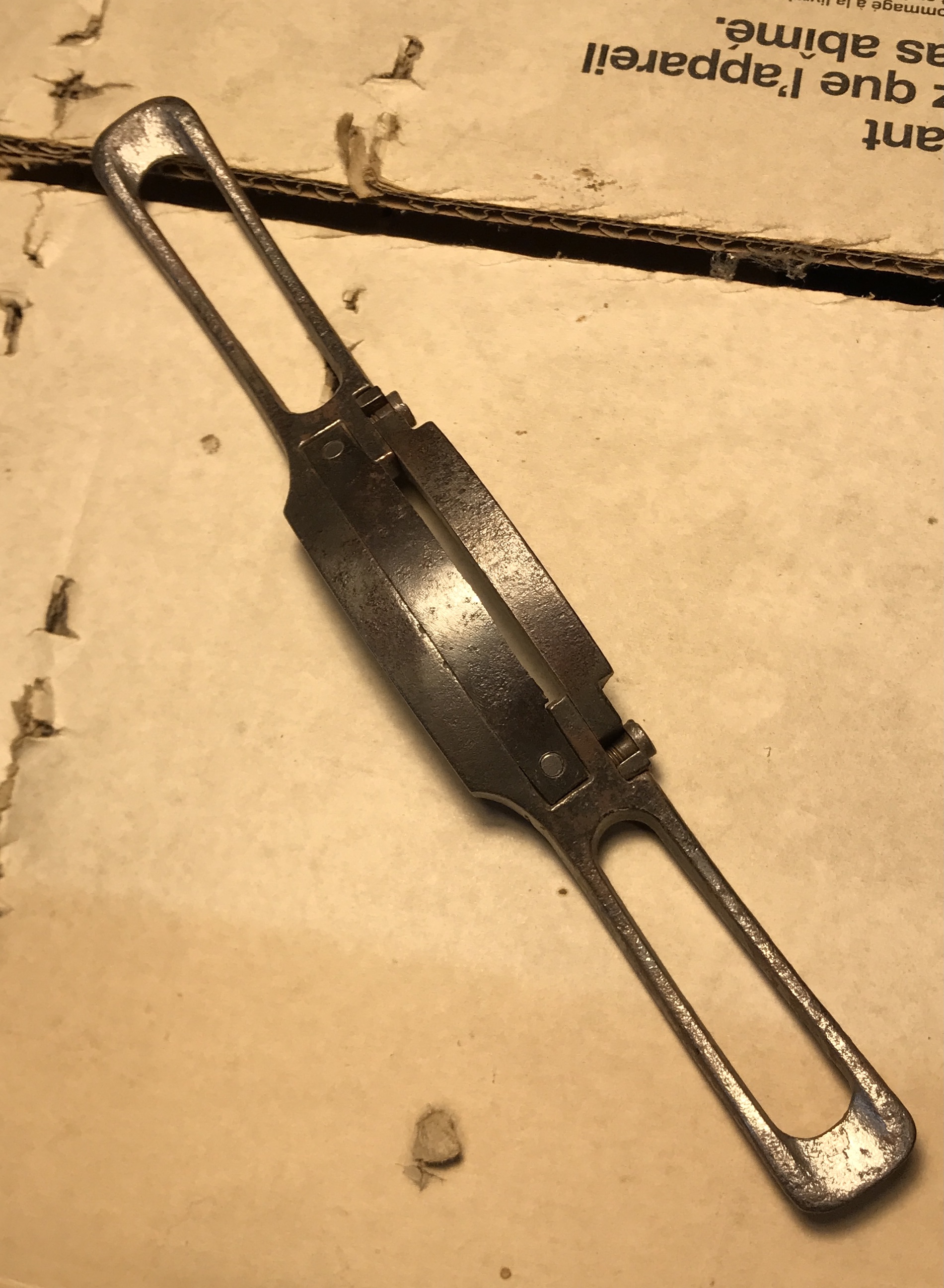
A few of the tools caught my eye as potential restoration projects. The brace, the monkey wrench and an unknown tool. The unknown tool is for cutting round tenons on wagon wheel spokes. It is also known as a hollow auger. It has a patent date of '78, 1878. Searching patents.google.com yielded a patent, 203,384 issued to Geo. N. Stearns of Syracuse, NY. The first page of the patent is shown below. The tool may have been handed down to William from his father. I decided to tackle its restoration first.
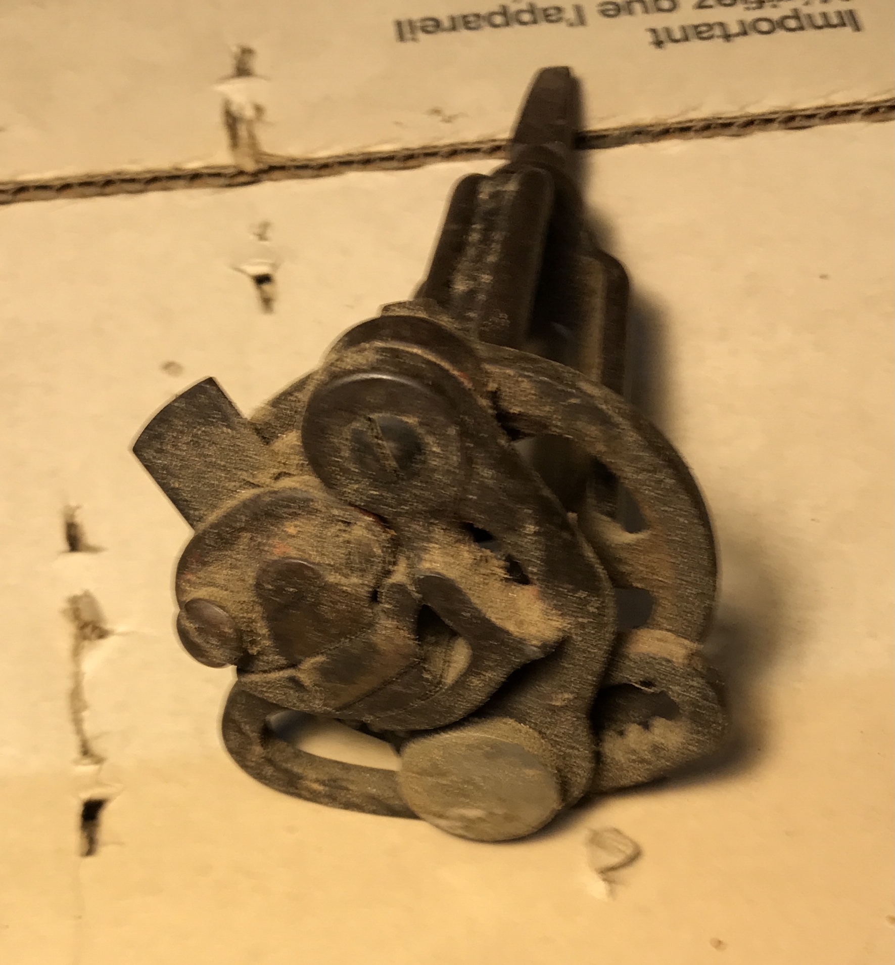
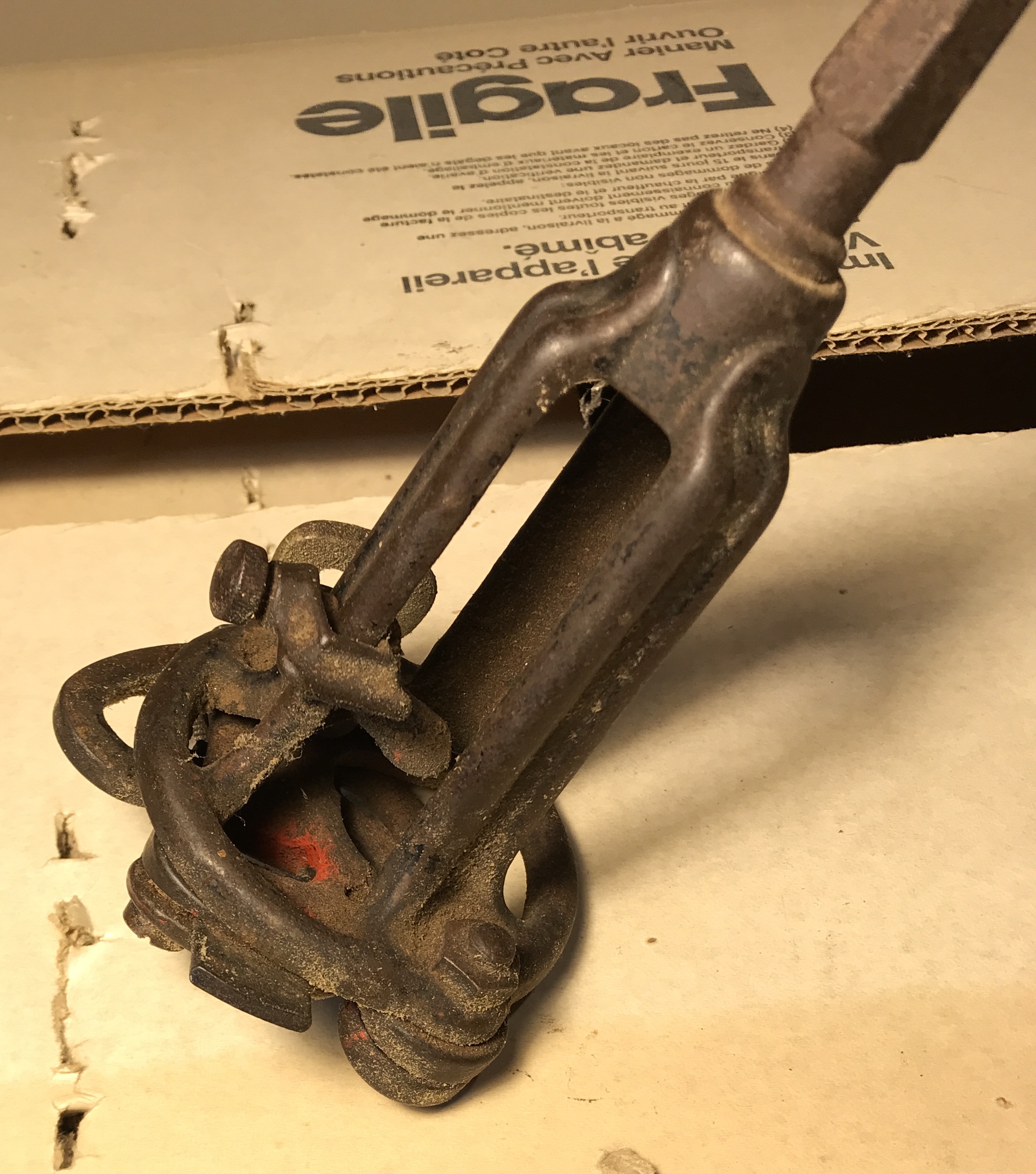
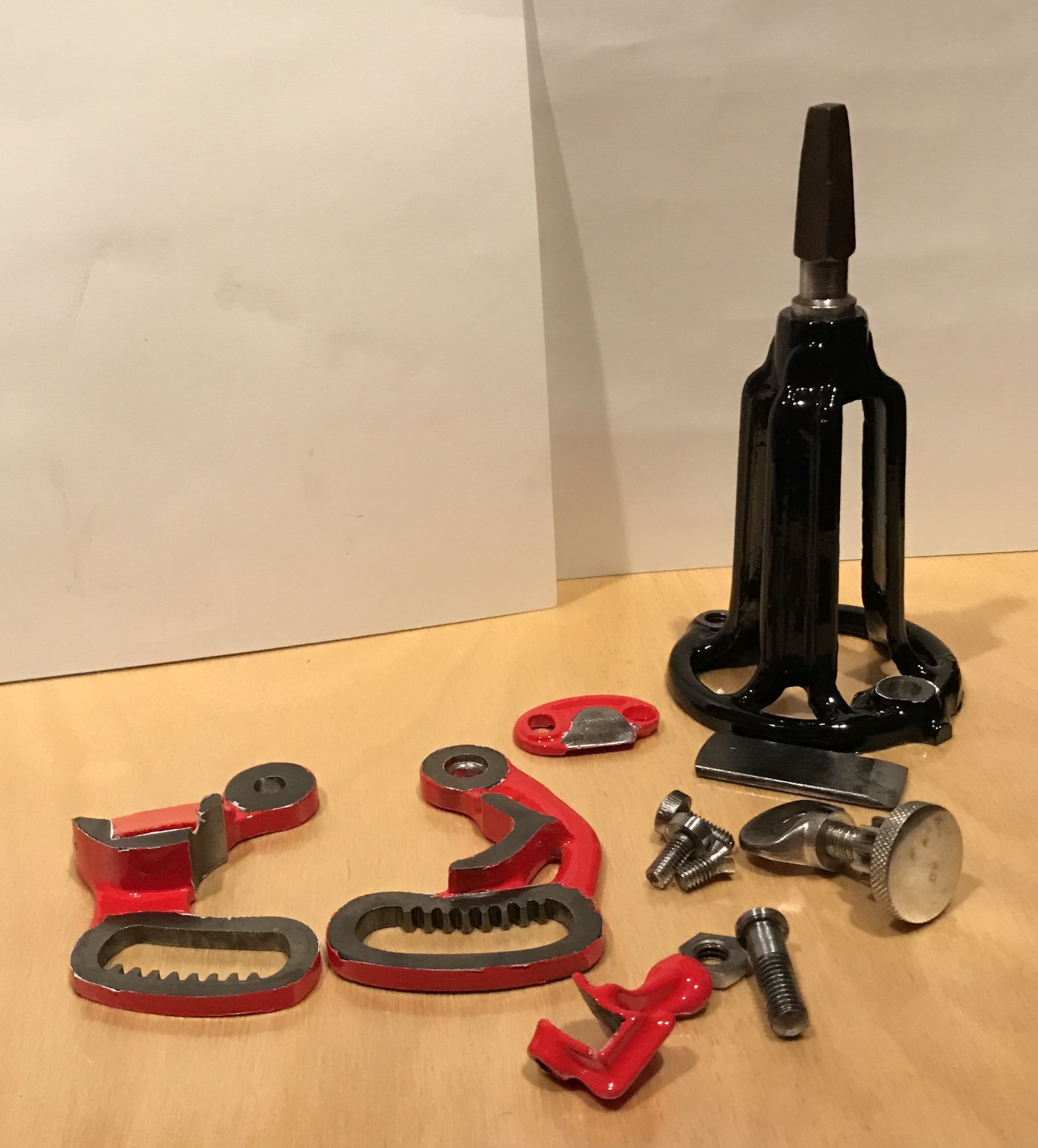
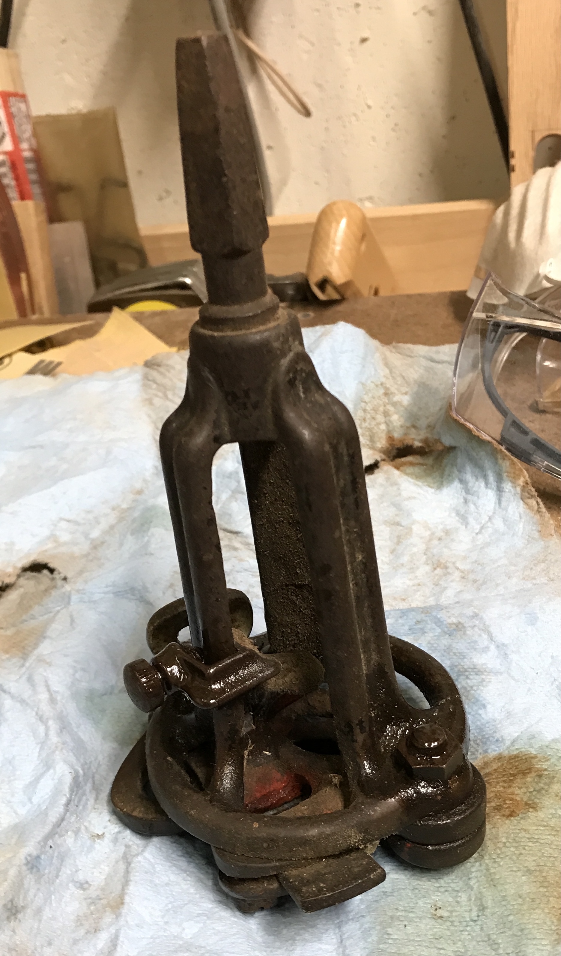
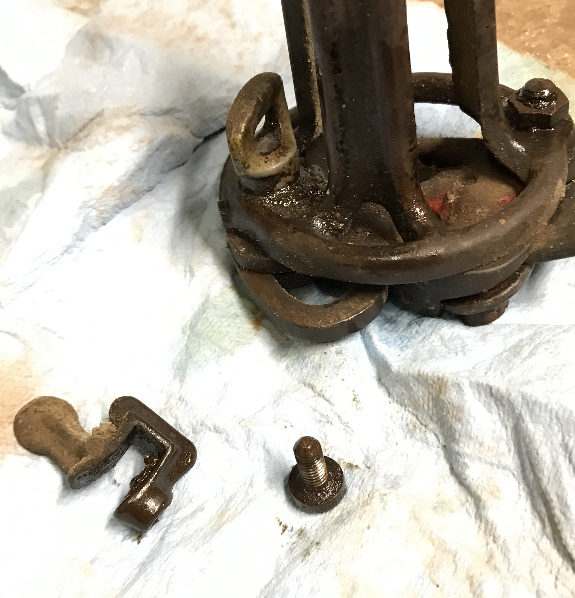
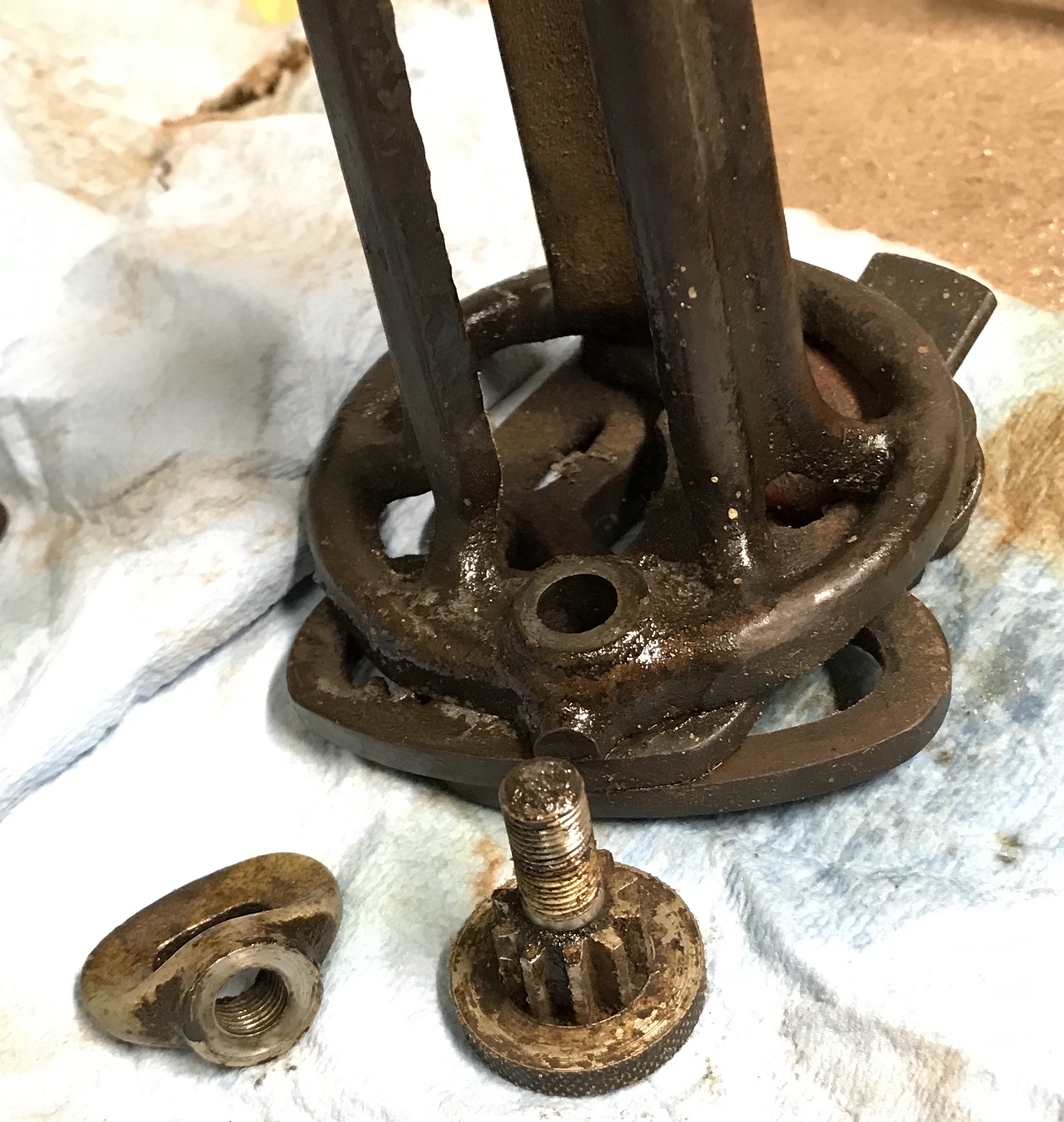
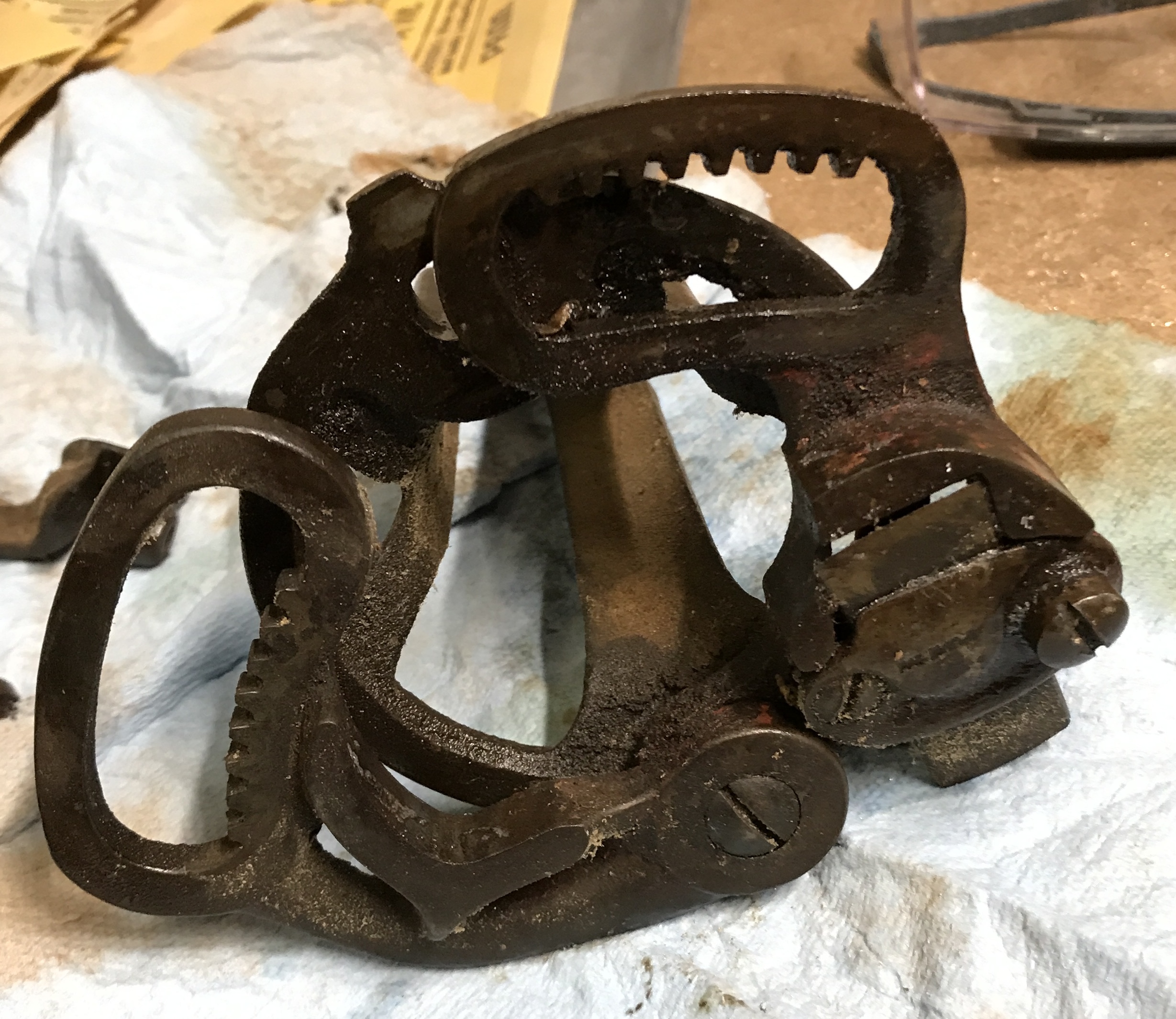
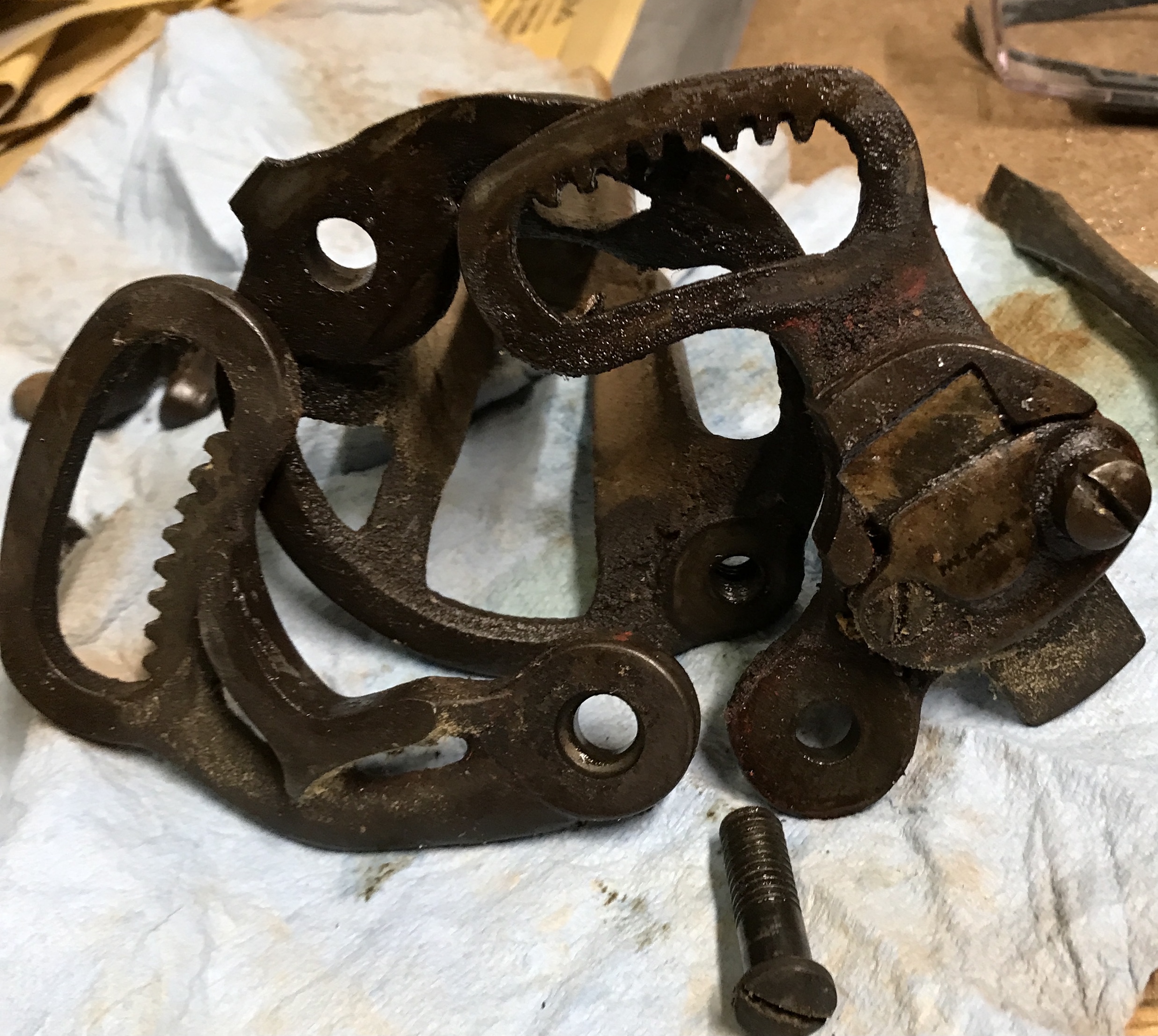
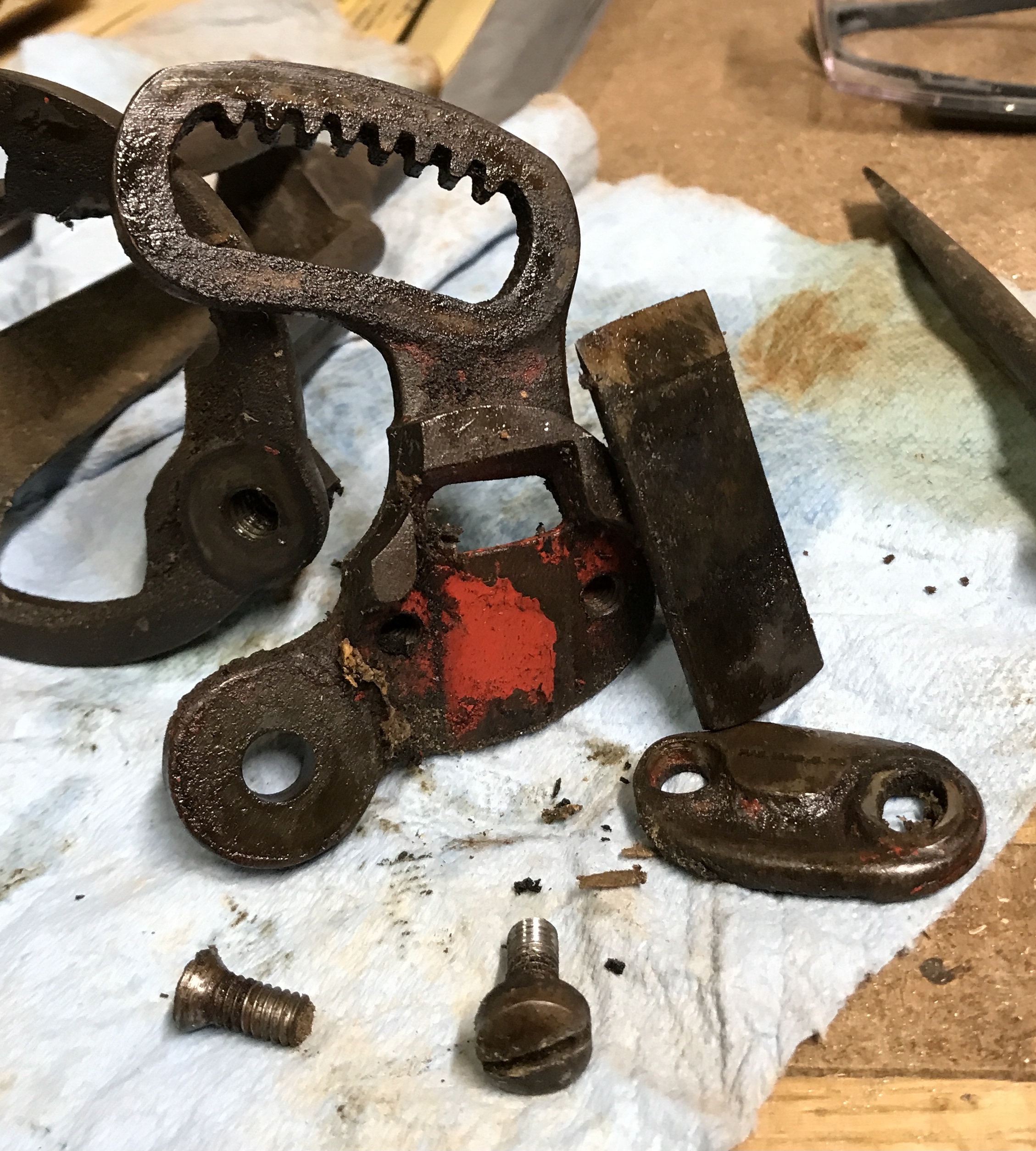
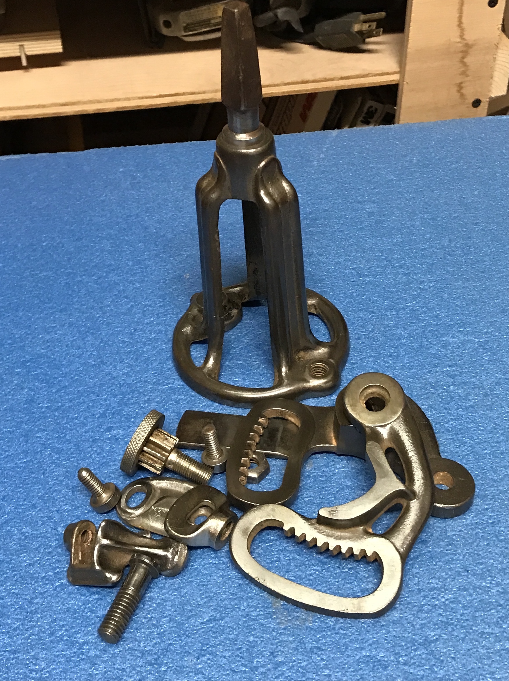
The tool was sprayed with WD-40 where there were screws. The screws were removed. Some parts seem to have been painted black and some red. Must have been a pretty tool when new. The second set of photos document the disassembly.
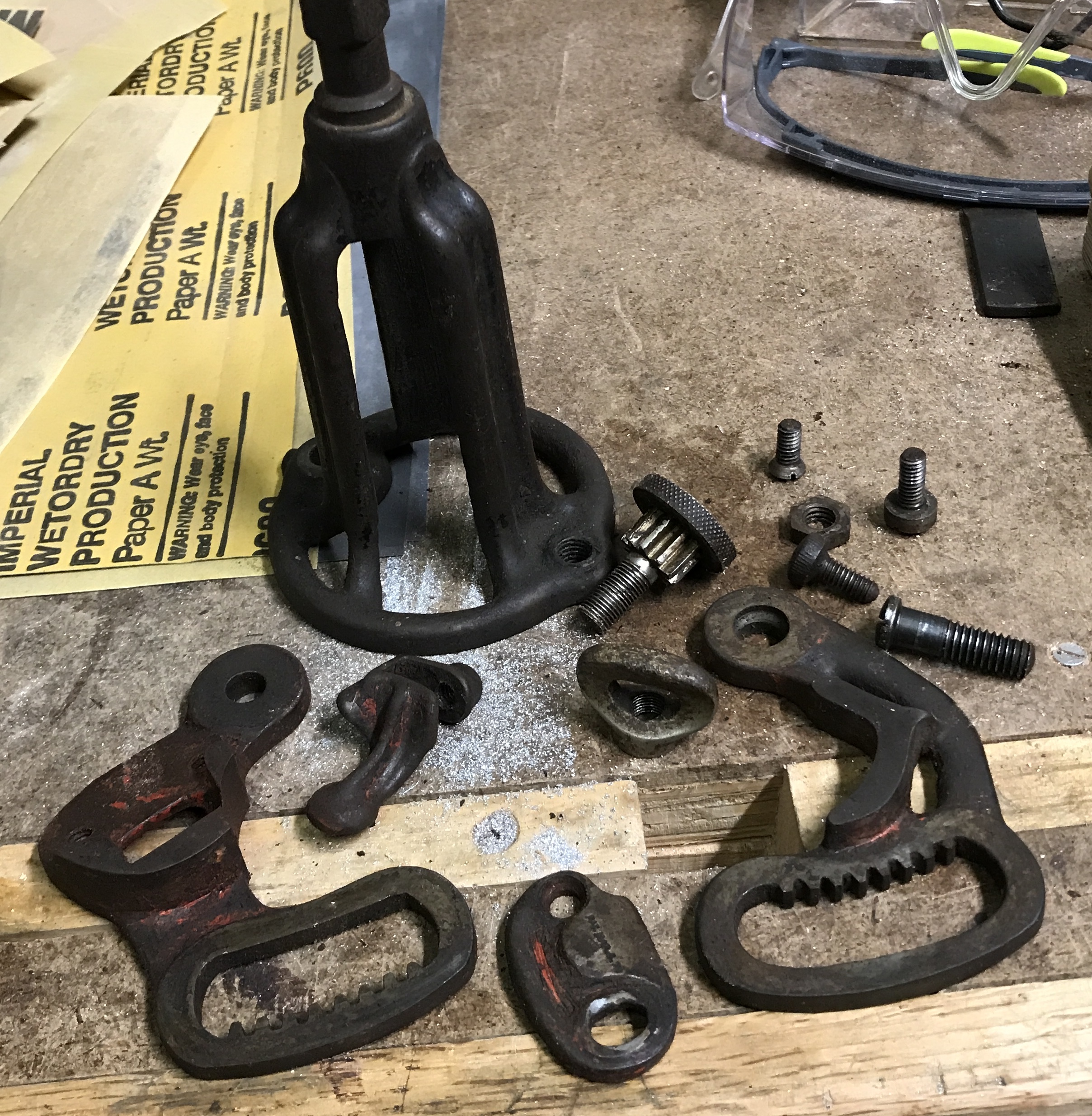
I used an old screwdriver from the same box and a toothbrush to remove most of the hundred years of gunk and grime. The roughly cleaned parts are shown again below. Zep Purple Degreaser was purchased for cleaning as were red and black spray paint.
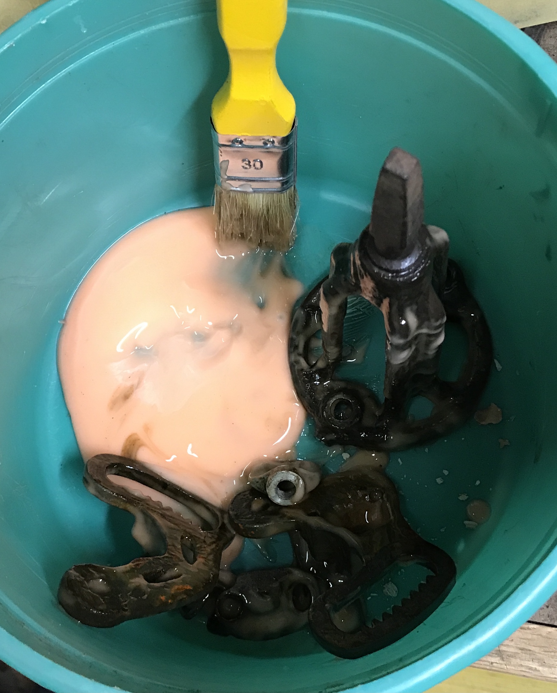
All of the parts except the screws showed evidence of either black or red paint. I brought in an old container of Citri-Strip. I painted this on the parts with hints of paint. It is supposed to sit for 1 to 24 hours. The photo shows a bucketful of stripping parts. After three hours most of the paint came off with a tooth brush. The parts were recoated with the Citri-Strip and left until tomorrow.
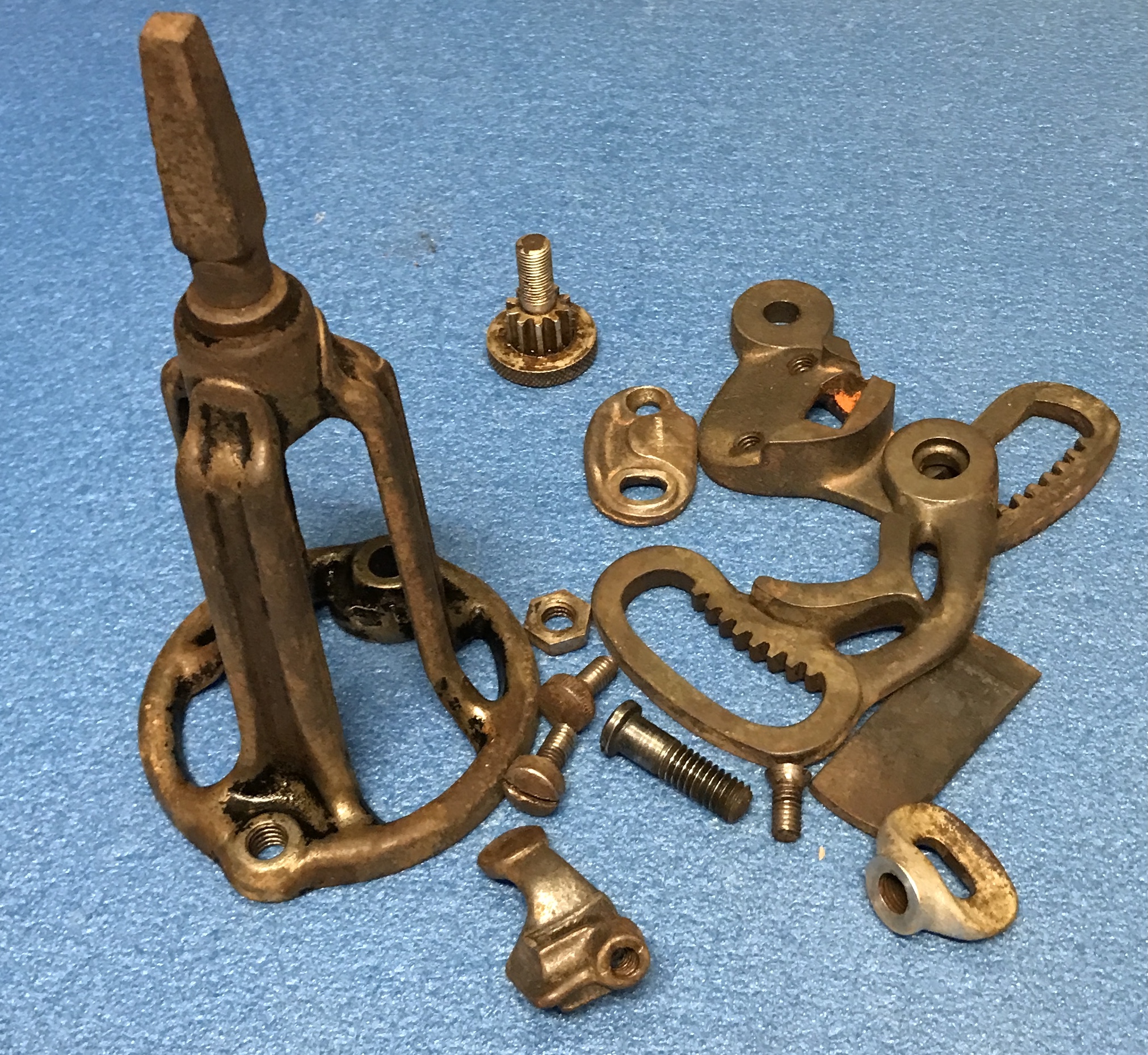
The Citri-Strip was washed off with water and the parts were thoroughly rinsed. The parts were the sprayed with Zep degreasing cleaner. After a few minutes the parts were brushed with an wire brush. Most of the gunk is gone, but there is still evidence of black and red paint. The photo below shows the parts after cleaning.
A wire wheel was installed in the small drill press. The parts were cleaned of rust with the wheel. There were places where the wheel could not hit the metal. For instance the inside of the main housing could not be touched and still had significant black paint. The photo below shows the nice shine on the parts after the wire wheel.
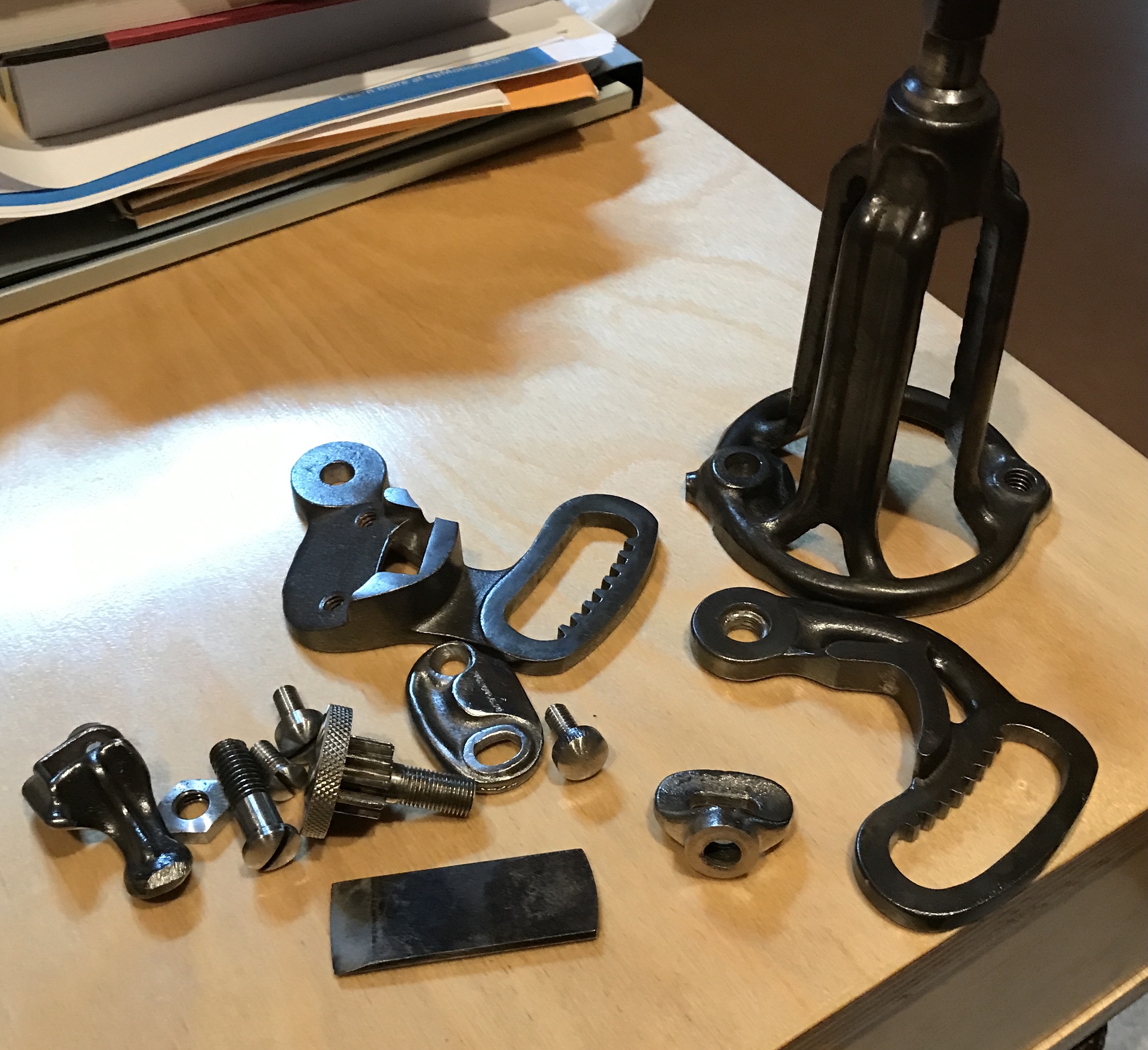
In order to get into the smaller spaces the Dremel was fitted with a wire brush. It removed all of the black paint remaining on the inside of the housing. It also removed red paint and was able to clean between the gear teeth. There were a few chamfered holes that this smaller wheel could not touch. A small grinding bit was installed in the Dremel. This was able to get into the remaining spots. Taps were used to clean up the screw holes. Most were 12-24, but one was 5/16-18. Dies were used to chase the threads on the screws. The screws were mounted in the lathe vise, filed, and sanded. The slots were cleaned out with a dental pick. They were still packed with gunk. The screw with the gear teeth was also cleaned with the dental pick. It is a non-standard thread as is its "wing" nut. The cutting tool was sharpened on a stone. The parts ready for painting are shown below.
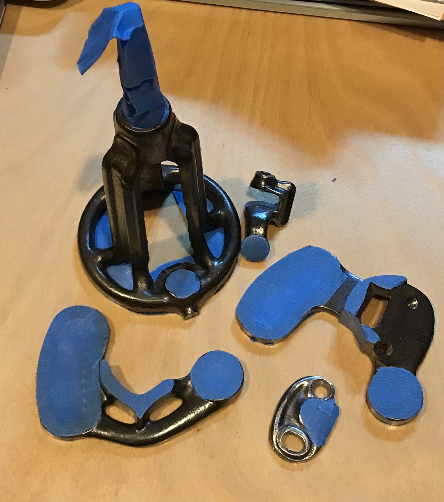
The machined surfaces of the five parts that should be painted were defined. These surfaces were covered with painters tape. The edges were cut to the line of the machined surface with an Exacto knife. The knife was dull and had to be sharpened on a stone. The picture below shows the taped parts ready for painting. (As soon as I can find an appropriate box to serve as a spray booth.) Three threaded holes need to be filled with paper towel prior to painting.
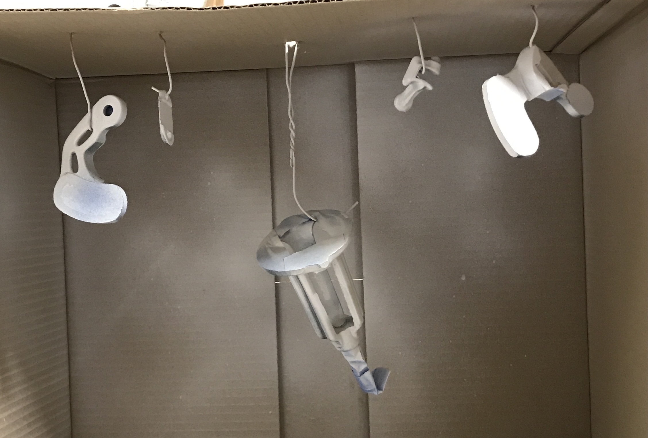
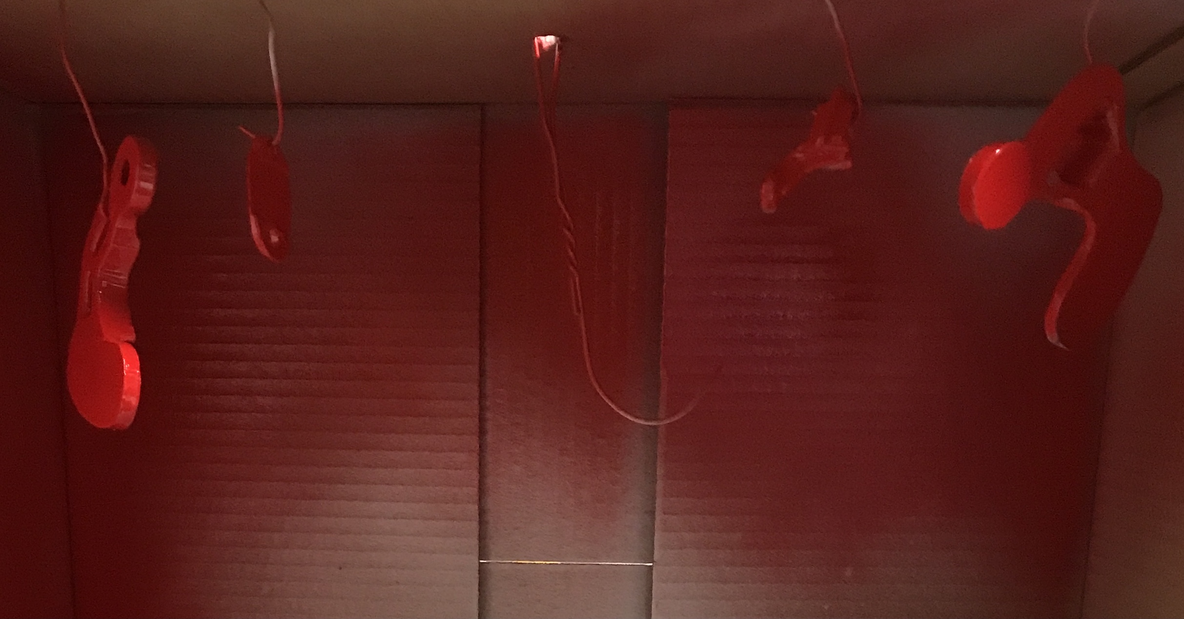
A box was acquired from Costco on Pearl Harbor Day. One hangar and four short lengths of copper wire were bent into shape to hang the five parts. All parts were sprayed with white primer twice. The picture below shows the primed parts pendant in the spray painting booth.
The red paint was used next on the four parts excluding the main housing. All parts were sprayed twice with the red paint. Finally the main housing was sprayed with black paint, two coats. Both the red and black painted parts had to dry overnight before they could be handled.
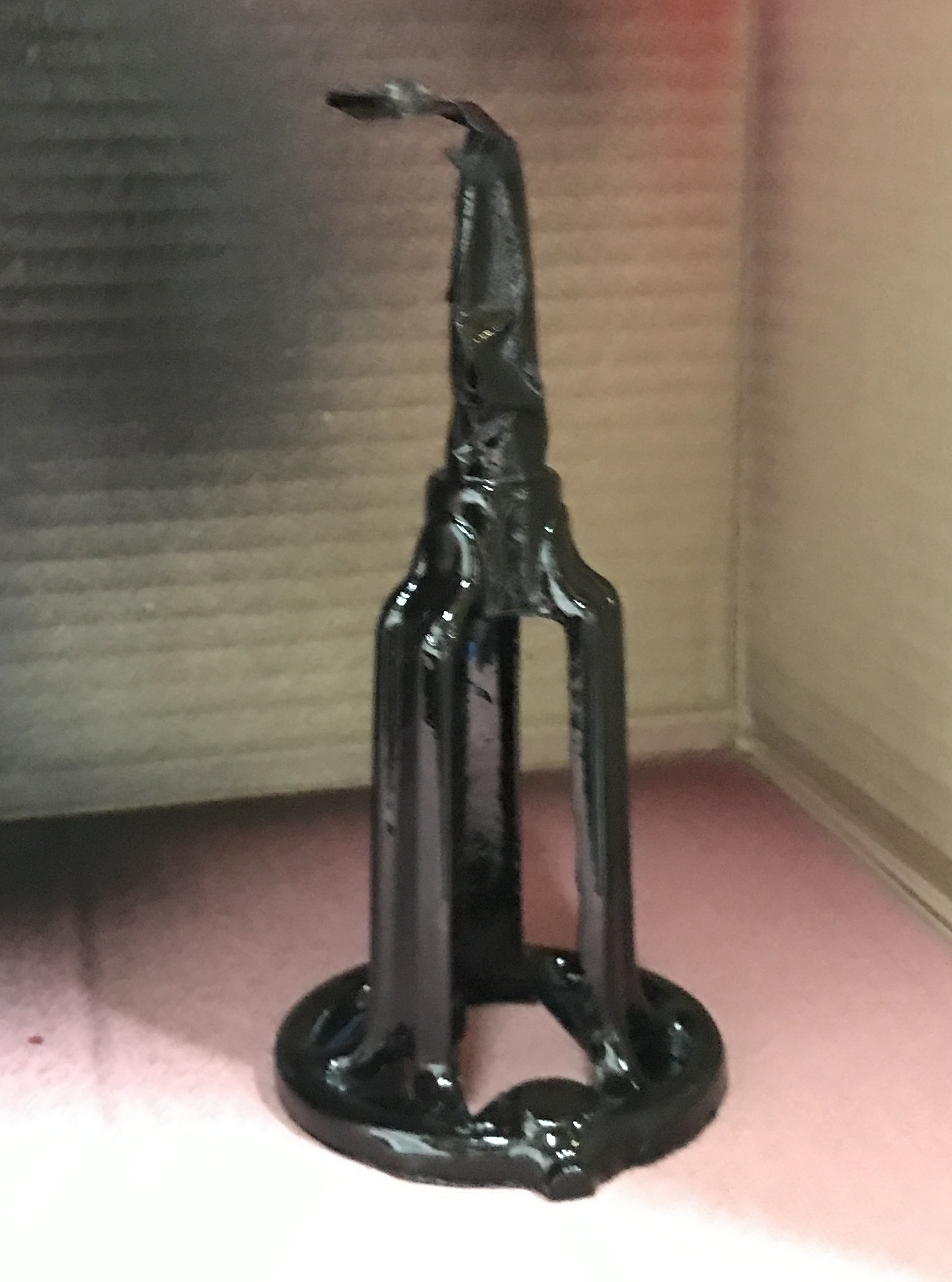
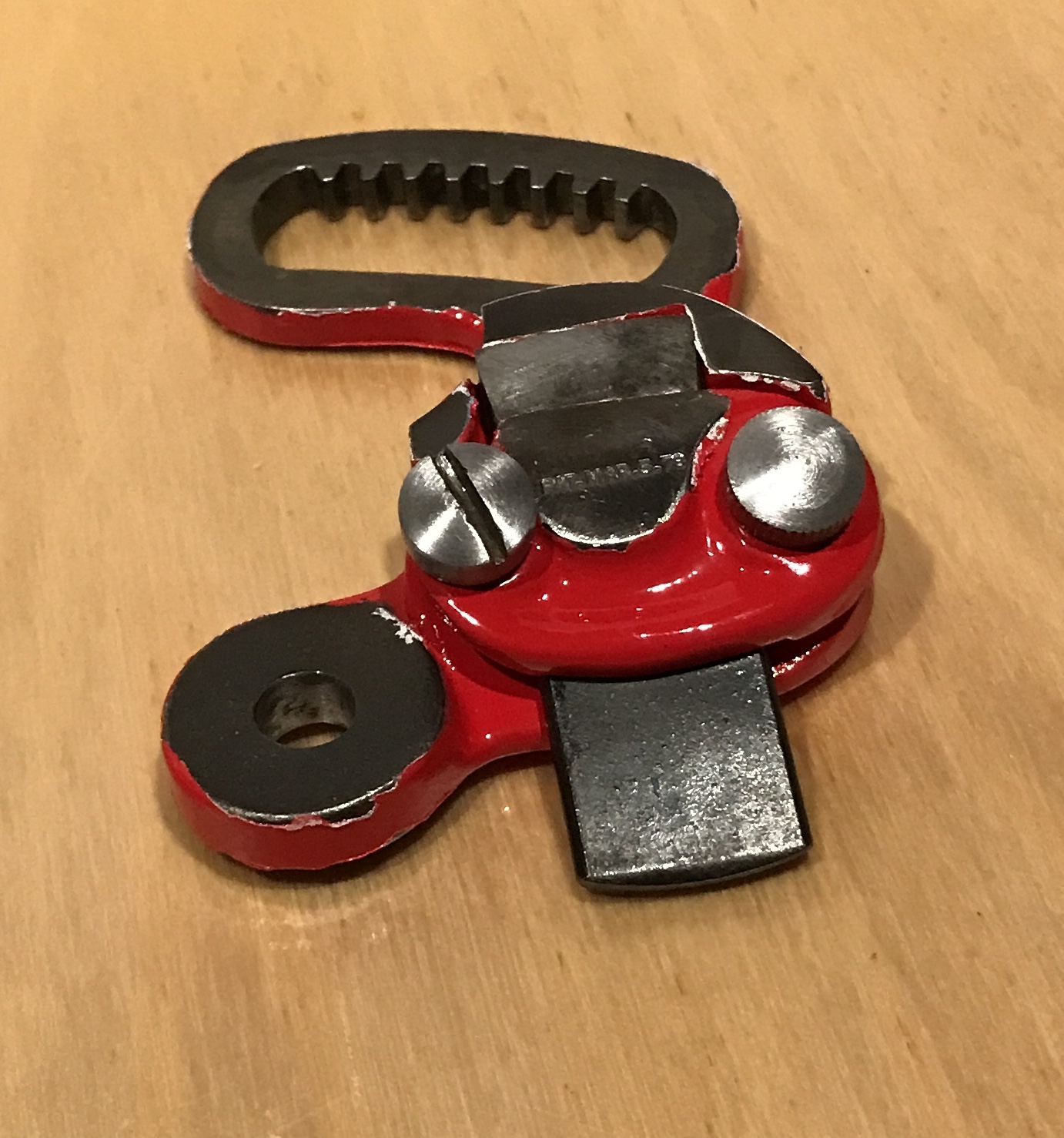
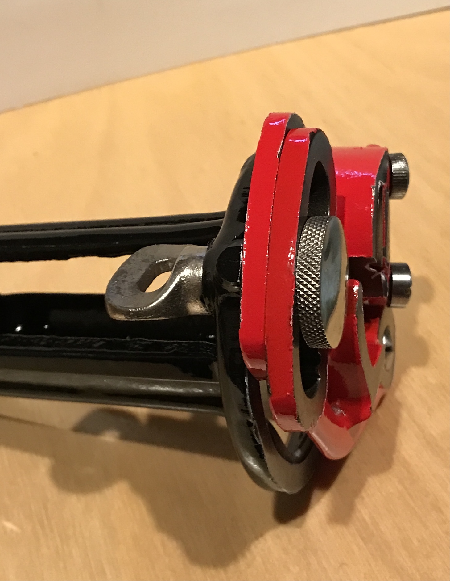
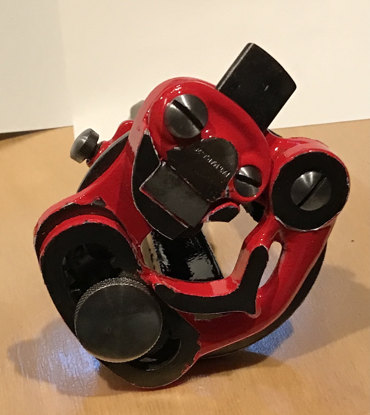
And here are the same parts after removing the tape and ready to assemble.
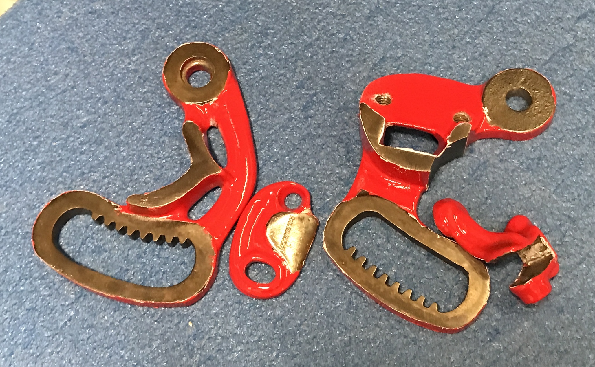
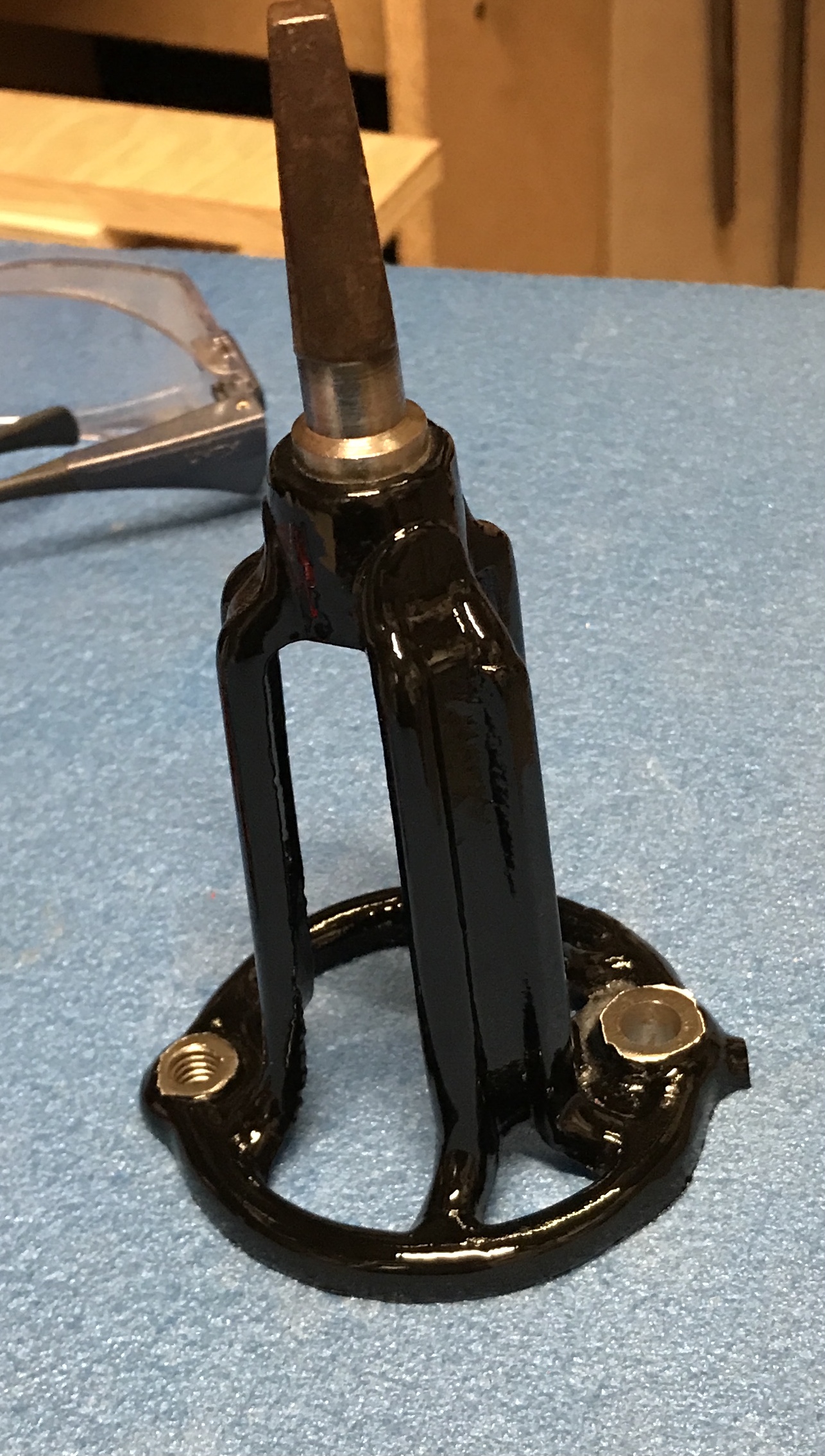
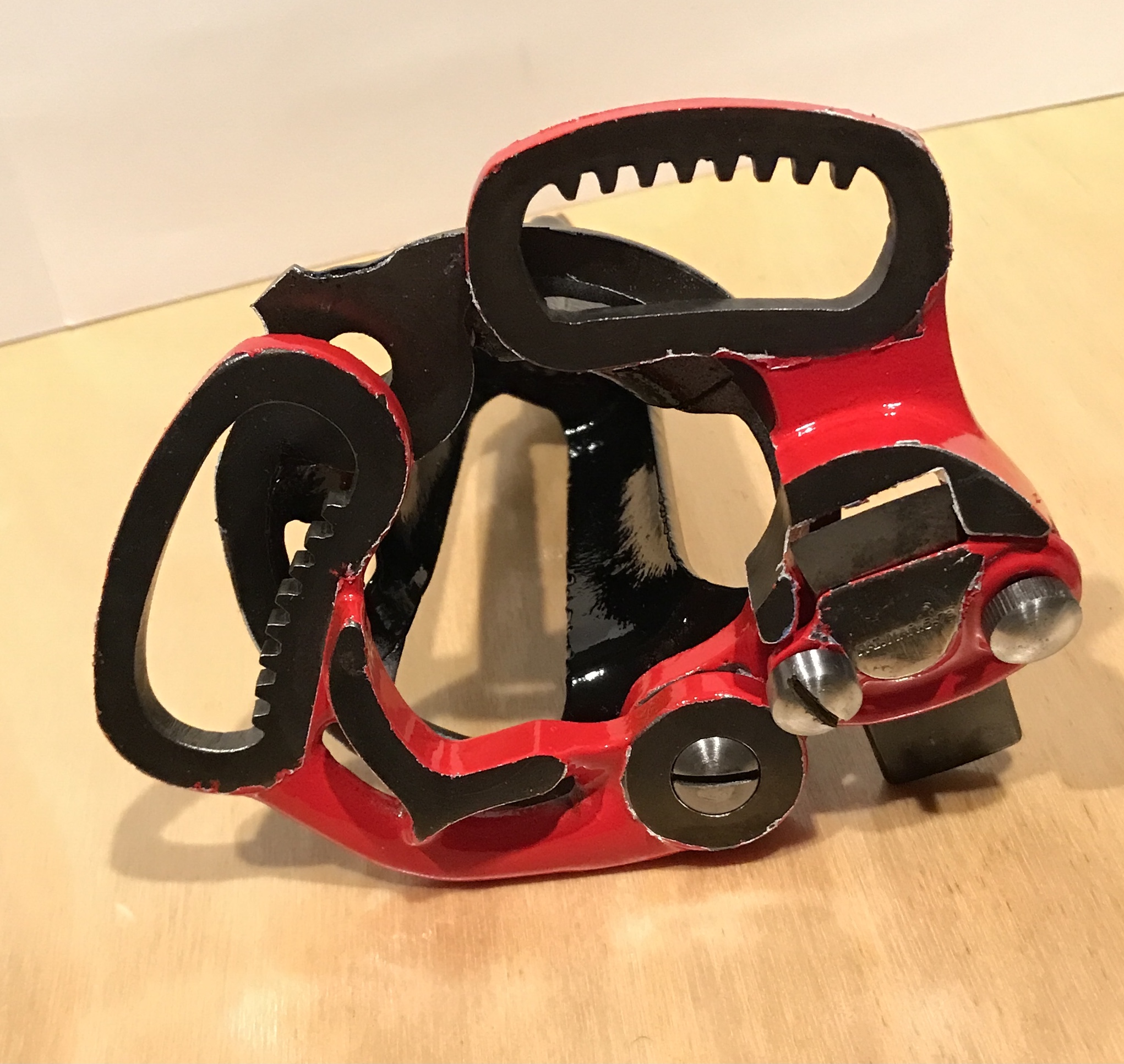
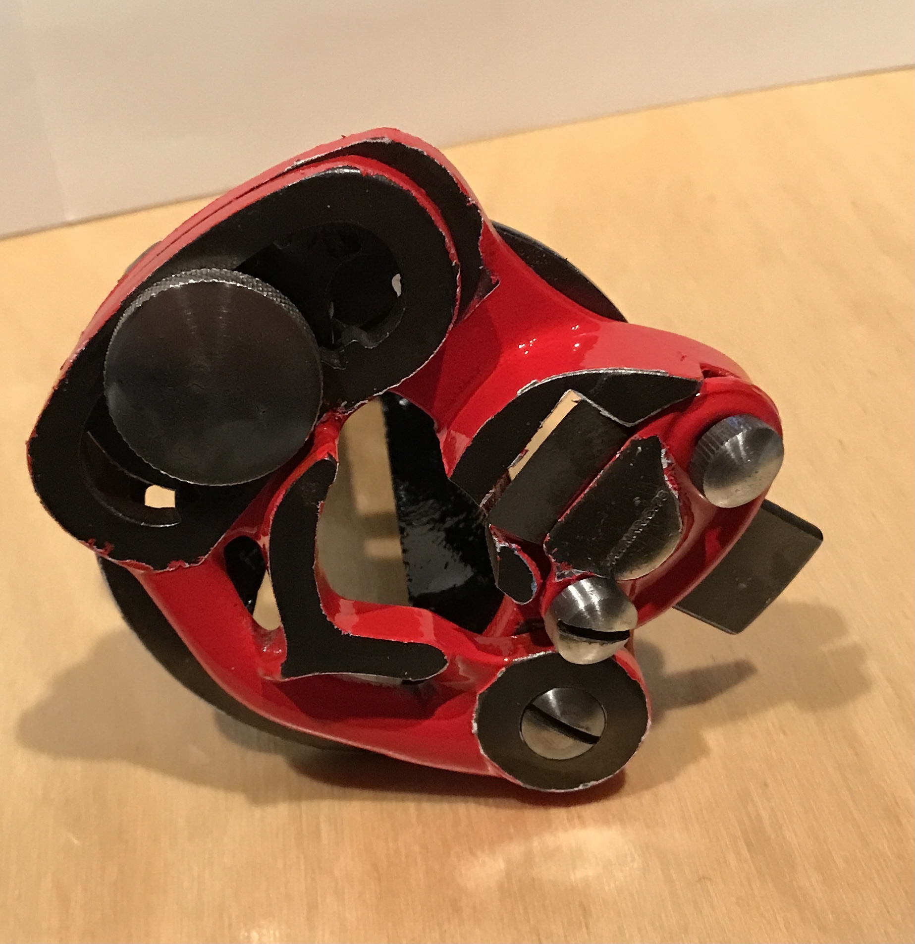
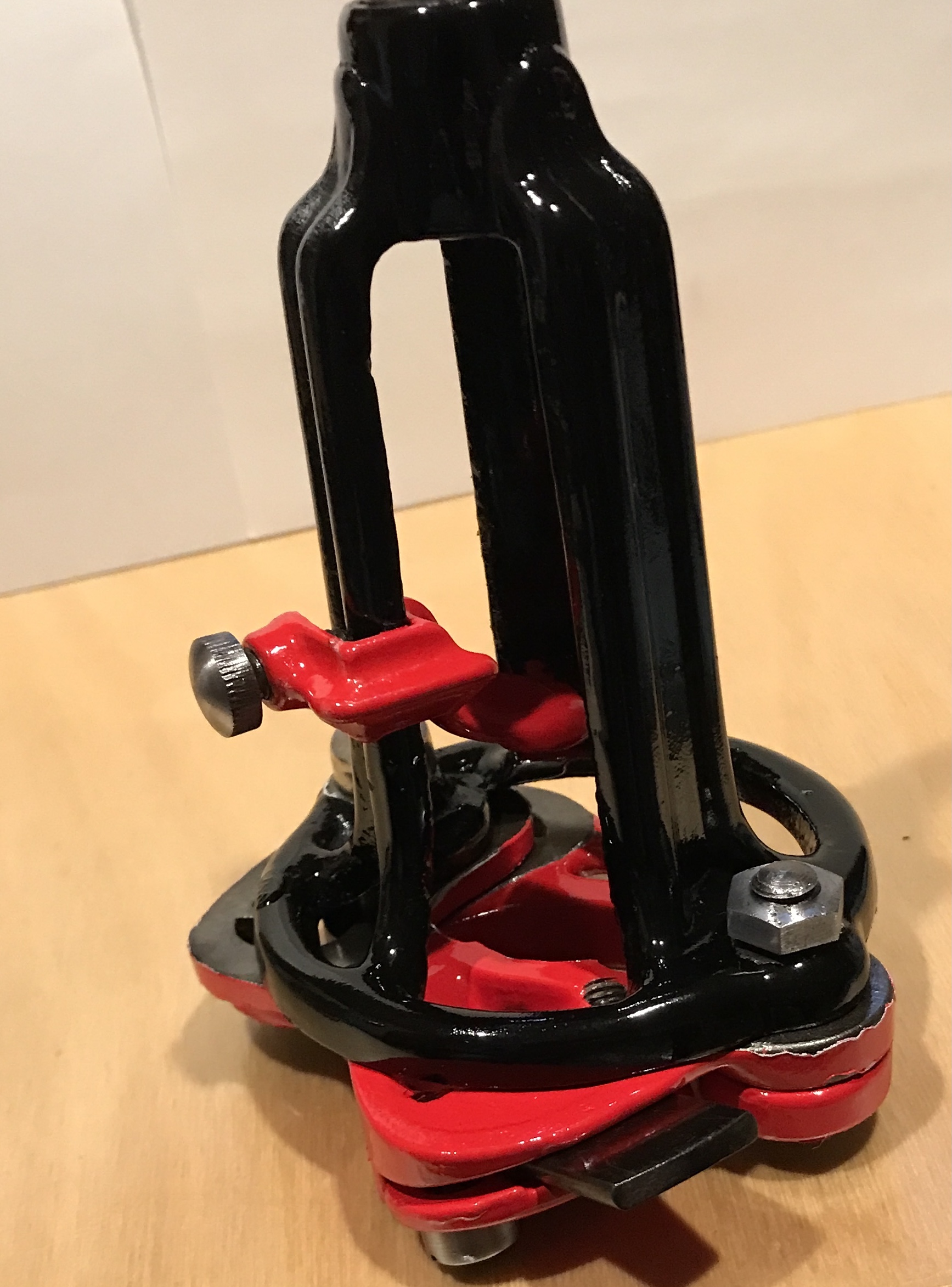
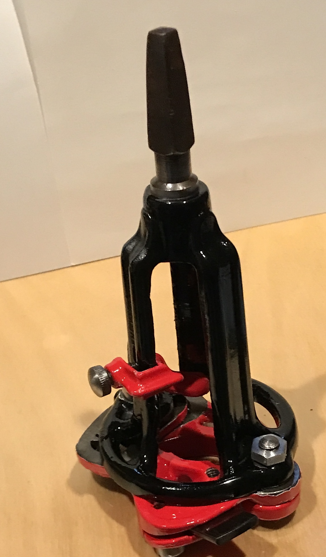
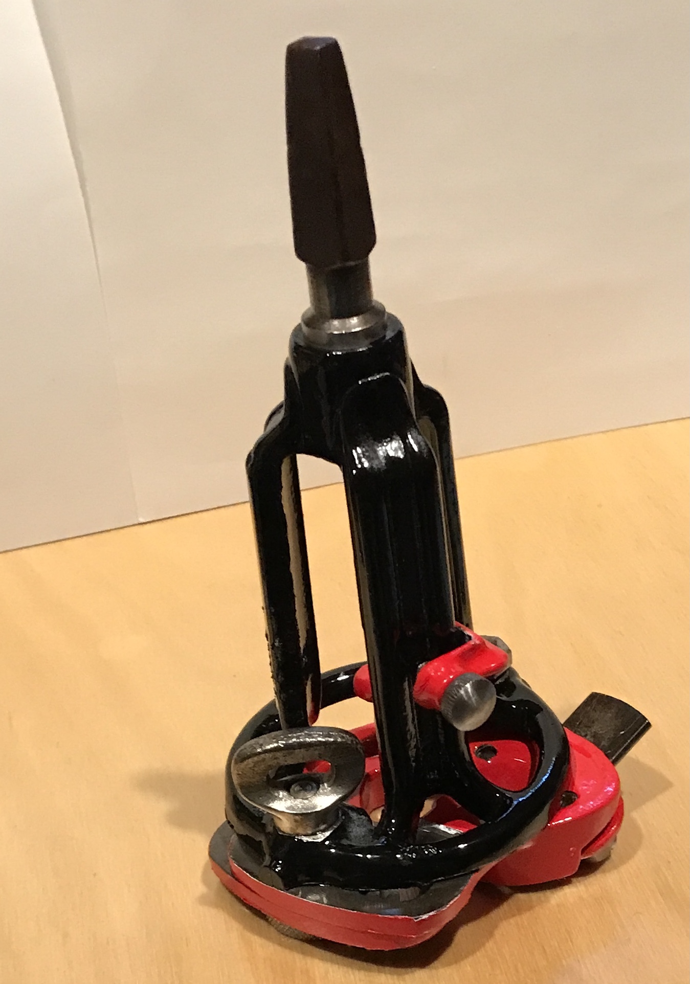
The assembly was straightforward. The blade holder with blade was attached to one of the swinging arms with two screws. The picture below shows the incorrect assembly. The slotted screw goes in the right hole, the knurled screw is for the stop, and a round head screw goes on the left. This correct arrangement is seen in the last photo. The two swinging arms were attached with the long screw and a nut was placed on the back side to lock the screw in place. The adjusting screw and gear were attached to the opposite side of the housing. Finally, the stop was attached to one arm of the housing. A little oil was used on all of the screws.